


5
MAINTENANCE OF THE MACHINE
CHANGING THE PARTS
Before carrying out any maintenance work, disconnect the appliance from the gas and electric
supply.
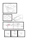
To replace different components such as burners, taps and electrical parts you must take out the hob from
the kitchen unit by releasing the fixing hooks, unscrew the fixing screws of the burners on the work top,
unscrew the fixing nuts of the electric plates which are visible on the lower part of the hob and remove the
worktop in order to carry out the replacement of the defective parts.
NOTE: If the taps need replacing you also need to unscrew the two fixing screws of the gas ramp at the
bottom of the hob which are found on the upper part of the latter.
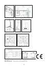
For appliances equipped with automatic “ON” switches you must dismantle the “ON” switch chain before
replacing the taps.
You are advised to change the seal on the tap every time you replace a tap in order to ensure a perfect hold
between the body and ramp.
WARNING: The electric cable which is provided with the appliance is connected to the appliance with a type
X connection and thus can be replaced with the same type of cable as that installed without using special
tools. In the event of wear or damage to the mains cable, replace it with :
Type/ section of mains cable H05VV-F 3x0,75 mm2 or H05RR-F 3x0,75 mm2
WARNING: If you replace the electric mains cable the installer must have the earth conductor about 2
cm longer than the phase conductors and must also take heed of the warnings regarding electric
connection.
Room ventilation – Location and venting.
ATTENTION: An exhaust fan may be used with the appliance; in each case it shall be installed in
conformity with the national standards in force.
ATTENTION: Exhaust hood operation may affect other vented appliances; in each case it shall be
installed in conformity with the national standards in force.
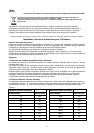
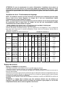
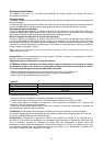
- CHANGING THE NOZZLES FOR USE WITH OTHER TYPES OF GAS:
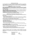
To change the nozzles of the burners use the following procedure:
Lift up the burners and unscrew the nozzles ( Fig. 9) using an adjustable spanner of 7 mm and change the
nozzles with those designed for the new gas supply according to the information given in TABLE A shown
below.
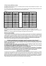
TABLE N°2: Adapting to different types of gas APPLIANCE CATEGORY: III
Burner Type of Gas Pressure Nozzle Nominal Charge Reduced Charge Diameter
diameter by-pass 1/100mm
mbar 1/100mm g/h l/h Kw kcal/h kw kcal/h
Town G110 8 145 - 227 1,00 860 0,30 258 27 reg
Auxiliary Natural G20 20 77 - 95 1,00 860 0,30 258 27 reg
Butane G30 28 50 73 - 1,00 860 0,30 258 27
Propane G31 37 50 71 - 1,00 860 0,30 258 27
Town G110 8 192 - 397 1,75 1505 0,44 378 31 reg
Semi- Natural G20 20 101 - 167 1,75 1505 0,44 378 31 reg
Rapid Butane G30 28 66 127 - 1,75 1505 0,44 378 31
Propane G31 37 66 125 - 1,75 1505 0,44 378 31
Town G110 8 280 - 681 3 2580 0,75 645 42 reg
Natural G20 20 129 - 286 3 2580 0,75 645 42 reg
Rapid Butane G30 28 87 218 - 3 2580 0,75 645 42
Propane G31 37 87 214 - 3 2580 0,75 645 42
Town G110 8 130 - 181 0,8 688 0,30 258 27 reg
Dual Natural G20 20 70 - 76 0,8 688 0,30 258 27 reg
burner Butane G30 28 46 211 - 0,8 688 0,30 258 27
inner Propane G31 37 46 207 - 0,8 688 0,30 258 27
Town G110 8 2x300 - 885 4,4 3784 1.8 1548 65 reg
Dual Natural G20 20 2x110 - 419 4,4 3784 1.8 1548 65 reg
burner Butane G30 28 2x69 298 - 4,1 3526 1.8 1548 65
outer Propane G31 37 2x69 293 - 4,1 3526 1.8 1548 65
CAUTION: save the orifices removed from the appliance for future use
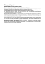
Regulation of burners
Regulation of the "MINIMUM" on the burners
To regulate the minimum on the burners carry out the following procedure indicated below:
1) Turn on the burner and put the knob onto position MINIMUM ( small flame ).
2) Remove the knob ( Fig. 10) of the tap which is set for standard pressure. The knob is found on the bar of
the tap itself.