


2
WARNING
Read this instruction booklet before installing and using the appliance.
The manufacturer will not be responsible for any damage to property or to persons caused by incorrect
installation or improper use of the appliance.
The manufacturer reserves the right to make changes to its products when considered necessary and useful, without
affecting the essential safety and operating characteristics.
This appliance has been designed for non-professional, domestic use only.
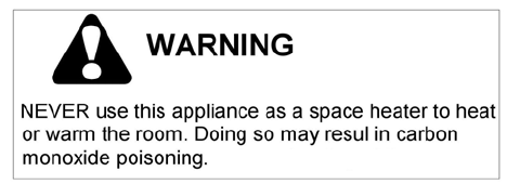
Warning: do not use this appliance to heat a room.
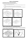
Installation instructions
This appliance shall only be installed by an authorized person. This appliance shall be installed in accordance
with the manufacturer’s installation instructions, IMPORTANT: this appliance must be installed in accordance
with the norms & standards of the country where it will be installed.
The installation of this appliance must conform to local codes and ordinances. In the absence of local codes,
Installations must conforms to American National Standards, National Fuel Gas Code ANSI Z223.1 – latest
edition** or B149.1.
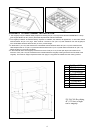
If local codes permit, a flexible metal appliance connection with the new AGA or CGA certified design, max. 5
feet (1,5 m) long, ½” I.D. is recommended for connecting this appliance to the gas supply line. Do not bend or
damage the flexible connector when moving the appliance. The pressure regulator has ½” female pipe thread.
The appropriate fitting must be determined based on the size of your gas supply line, the flexible metal
connector and the shutoff valve.
The appliance, when installed, must be electrically grounded in accordance with local codes or, in the absence
of local codes, with the National Electrical Code, ANSI/NFPA 70.
The appliance and its individual shutoff valve must be disconnected from the gas supply piping system any
pressure testing of that system at test pressure in excess of ½ psi (3,5 kPa).
The appliance must be isolated from the gas supply piping system by closing its individual manual shutoff valve
during any pressure testing of the gas supply piping system at test pressures equal to or less than ½ psi (3.5
kPa).
For use with a pressure regulator. The regulator supplied must be used with this appliance; it shall be properly
installed in order to be accessible when appliance is installed in its final location.
The gas appliance pressure regulator must be set for the gas with which the appliance is used.
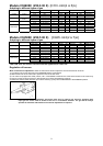
This appliance can be used with Natural Gas and LP Gas. It is shipped from the factory adjusted for use with
Natural Gas: CONVERSION FIXED ORIFICES ARE LOCATED IN THE LITERATURE PACK SUPPLIED WITH THE
UNIT.
A gas nozzle kit for the change of type of gas are contained inside the package tigether with the gas
appliance installation kit and instruction booklet.
The maximum inlet gas supply pressure incoming to the gas appliance pressure regulator is 20’’ water column
(5 kPa) .
The minimum gas supply pressure for checking the regulator setting shall be at least 1“ w.c. (249 Pa) above the
inlet specified manifold pressure to the appliance (this operating pressure is 4” w.c. (1.00 kPa) for Natural Gas
and 11” w.c. (2.75 kPa) for LP Gas.
ATTENTION: A manual valve shall be installed in an accessible location in the gas line external to the appliance
for the purpose of turning on or shutting off gas to the appliance
WARNING: Do not use aerosol sprays in the vicinity of this appliance while it is in operation
Requirements
Room ventilation – Location and venting.
ATTENTION: An exhaust fan may be used with the appliance; in each case it shall be installed in conformity with
the national standards in force.
ATTENTION: Exhaust hood operation may affect other vented appliances; in each case it shall be installed in
conformity with the national standards in force.