


7
GAS CONNECTION
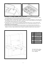
All gas connections must be made according to national and local codes. This gas supply (service) line must be the
same size or greater than the inlet line of the appliance. This range uses a 1/2" NPT (see fig. in this chapter for details of
gas connections installations) inlet. Sealant on ali pipe joints must be resistive to LP gas.
1. Manual Shut-off Valve:
This installer-supplied valve must be installed in the gas service line ahead of the appliance in the gas stream and in
a position where it can be reached quickly in the event of an emergency. The manual shut-off valve shall be installed
properly in order to be accessible when appliance is installed in definitive position. In Massachusetts: A 'T' handle
type manual gas valve must be installed in the gas supply line to this appliance.
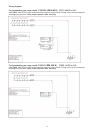
2. Pressure Regulator (see fig. in this chapter)
a) All cooking equipment must have a pressure regulator on the incoming service line for safe and efficient
operation, since service pressure may fluctuate with local demand. The pressure regulator is supplied
separately with the appliance; regulator has two female threads ½” NPT; it shall be installed properly in order
to be accessible when appliance is installed in definitive position.
b) Any conversion required must be performed by your dealer or a qualified licensed plumber or gas service
company. Please provide the service person with this manual before work is started on the range. (Gas
conversions are the responsibility of the dealer or end user.)
c) This range can be used with Natural or LP/Propane gas. It is shipped from the factory adjusted for use with
natural gas.
d) Manifold pressure should be checked with a manometer, natural gas requires 4.0" W.c.P. and LP/Propane
requires 11.0" W.C.P. Incoming line pressure upstream from the regulator must be 1" W.c.P. higher than the
manifold pressure in order to check the regulator. The regulator used on this range can withstand a
maximum input pressure of 1/2 PSI (14.0" W.c.P.) If the line pressure is in excess of that amount, a step-
down regulator will be required.
e) The appliance, its individuai shut-off valve, and pressure regulator must be disconnected from the gas
supply piping system during any pressure testing of that system at pressures in excess of 1/2 psig (3.45kPa).
f) The appliance must be isolated from the gas supply piping system by closing its individuai manual shut-off
valve during any pressure testing of the gas supply piping system at test pressures equal to or less than 1/2
psig (3.45 kPa).
3. Flexible Connections:
a) If the unit is to be installed with flexible couplings and/or quick disconnect fittings, the installer must use a
heavy-duty, AGA design-certified commerciai flexible connector of at least 1/2" (1.3 cm) ID NPT (with
suitable strain reliefs) in compliance with ANSI Z21.41 and Z21.69 standards.
b) In Massachusetts: The unit must be installed with a 36" (3-foot) long flexible gas connector.
c) In Canada: CAN 1-6.10-88 metal connectors for gas appliances and CAN 1-6.9 M79 quick disconnect
device for use with gas fuel.
CAUTlON: Leak testing of the appliance shall be conducted according to the manufacturer's instructions. Before placing
the oven into operation, always check for leaks with a soapy water solution or other acceptable method. DO NOT USE
AN
OPEN FLAME TO CHECK FOR LEAKS!
PERFORMANCE CHECKLlST
All burners are tested before leaving the factory. There are no adjustments for the burners if connected according to the
information on the rating plate. Check each burner for proper operations. Flames should be blue in all settings. If service
is required, contact your dealer for the name of their authorized servi ce agency. Gas conversions and initial installation
are not the responsibility of the manufacturer.
The installer should carry out the following performance checks. Refer to instructions below.
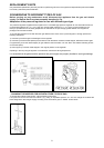
1. Check surface burner ignition.
2. Check low flame adjustment – surface burner valve center stem adjustment.
3. Check for gas leaks (odors) at ali gas connections.
FINAL PREPARATION
1. Some stainless steel parts may have a plastic protective wrap which must be removed. The interior of the oven
should be washed thoroughly with hot. soapy water to remove film residues and any installation dust or debris
before being used for food preparation, then rinsed and wiped dry. Solutions stronger than soap and water are
rarely needed.
2. Ali stainless steel body parts should be wiped with hot, soapy water and with a liquid deaner designed for this
materia!. If buildup occurs, do not use steel wool. abrasive cloths, cleaners, or powders! If it is necessary to
scrape stainless steel to remove encrusted materials, soak with hot, wet cloths to loosen the material, then use a
wood or nylon scraper. Do not use a metal knife, spatula, or any other metal tool to scrape stainless steel!
Scratches are almost impossible to remove.
NOTE: These installation instructions should remain with the unit for future reference. The electrical diagram is located in
the backside or the ccoker