


4
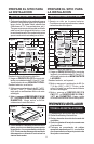
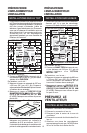
1. Remove roofing nails from the upper 2/3
of the shingles around the cutout area
and carefully lift the shingles to allow the
back flashing sheet on the blower hous-
ing to fit under them.
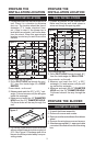
2. Center the blower ring in the 11" diam-
eter hole, making sure that the 1-1/4"
diameter electrical wiring hole aligns with
the hole in the wiring box.
3. Attach the blower to the roof with the six
screws provided. All six holes in the back
panel must be filled, or any moisture that
may get inside the housing could leak
into the house.
4. Using a good grade of roofing cement,
seal all of the shingles around the hous-
ing and flashing sheet as well as the
mounting screw heads.
5. Bring electrical wiring (from hood) through
the hole in the wiring box and secure it
according to local codes.
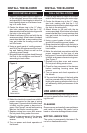
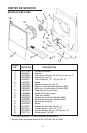
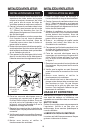
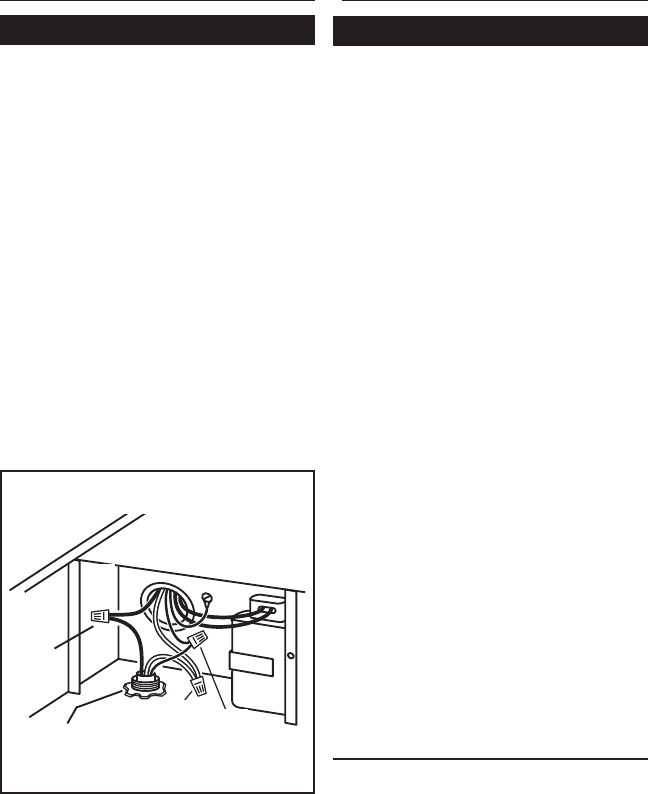
6. Make the electrical connections with the
proper connector for the type of wiring
being used. Connect white to white, black
to black, and the green or bare wire to
green. See Figure 4, as well as the wiring
label on the hood’s mounting plate.
7. Replace wiring box cover and screws.
Do not pinch wiring under the cover.
8. Check for free movement of the damper
before installing housing cover and
screws.
9. Turn on power and check operation of
the blower.
INSTALL THE BLOWER
ROOF INSTALLATIONS
120 VAC
LINE IN
BLACK
TO
BLACK
WHITE
TO
WHITE
GREEN
TO
GREEN
Figure 4
BLACK
TO
BLACK
WHITE
TO
WHITE
GREEN
TO
GREEN
120 VAC
WIRING
FROM HOOD
INSTALL THE BLOWER
WALL INSTALLATIONS
1. Place a large bead of caulk on the back
side of the housing along the outer edge.
2. Center the blower ring in the 11" diam-
eter hole, making sure that the 1-1/4"
diameter electrical wiring hole aligns with
the hole in the wiring box.
3. Attach blower to the wall with the six
screws provided. All six holes in the back
panel must be filled, or any moisture that
may get inside the housing could leak
into the house.
4. Using a good grade of caulk, seal all
around the mounting screw heads.
5. Bring electrical wiring through the hole in
the wiring box and secure it according to
local codes.
6. Make the electrical connections with the
proper connector for the type of wire
being used. Connect white to white, black
to black, and green or bare wire to green.
See Figure 4.
7. Replace wiring box cover and screws.
Do not pinch wiring under cover.
8. Check for free movement of the damper
before installing housing cover and
screws.
9. Turn on power and check operation of
the blower.
10.Top and side flanges of the back plate
may be covered with trim strips. Do not
block grille opening at bottom with trim. It
will adversely affect performance of the
blower.
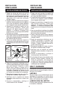
USE AND CARE
Disconnect electrical power supply and lock-
out service panel before cleaning or servic-
ing this unit.
CLEANING
Remove cover and carefully vacuum blower
and inside of housing. Be careful not to
bend or otherwise damage blower wheel.
MOTOR LUBRICATION
The motor is permanently lubricated. Do
not oil or disassemble motor.