


i, CAUTION: TurnoffGasand Emectridty
Before Proceedingwith the conversion;shut off
the{)assuppmytotheappliancepriortodiscono
nectingthe electricam power,
Shutofftheoutsidepropanetankgas valvetotherange,Re=
move range power cord from electrical outlet or turn breaker
off at breaker box, and turn all control knobs to the "OFF" posi=
tion.
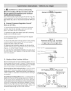
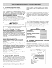
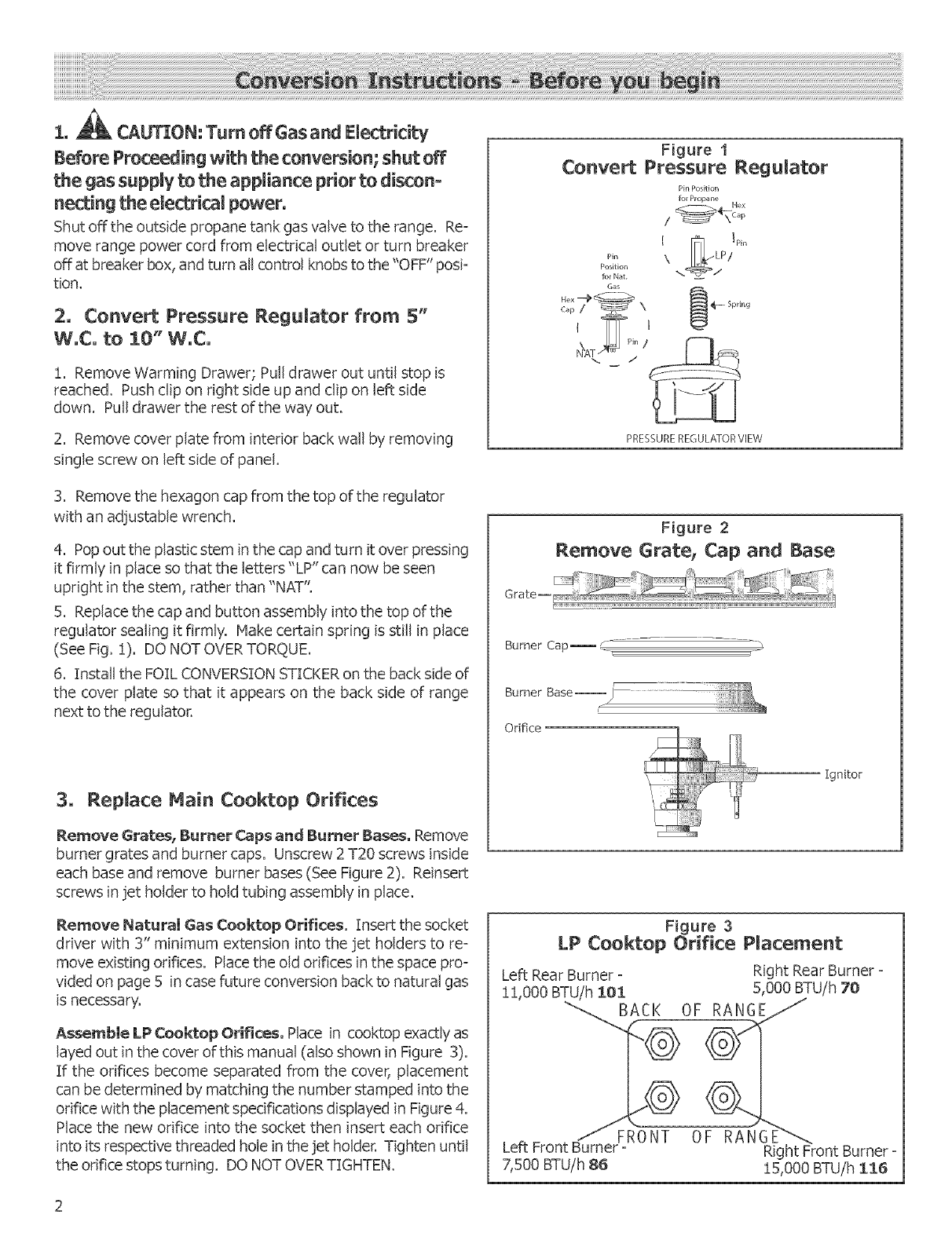
2° Convert Pressure Regulator from 5"
W°C° to 10" W°C°
!. Remove Warming Drawer; Pull drawer out until stop is
reached. Push clip on right side up and clip on left side
down. Pull drawer the rest of the way out.
2, Remove cover plate from interior back wall by removing
single screw on left side of panel
3. Remove the hexagon cap from the top of the regulator
with an adjustable wrench.
4. Pop out the plastic stem in the cap and turn it over pressing
it firmly in place so that the letters"LP" can now be seen
upright in the stem, rather than "NAT".
5. Replace the cap and button assembly into the top of the
regulator sealing it firmly. Make certain spring is still in place
(See Fig. !). DO NOT OVERTORQUE.
6. Install the FOIL CONVERSION STICKER on the back side of
the cover plate so that it appears on the back side of range
next to the regulator,
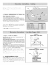
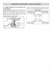
3, Repmace Main Cooktop Orifices
Remove Grates_ Burner Caps and Burner Bases, Remove
burnergratesand burnercaps,Unscrew 2T20 screwsinside
each base and remove burner bases (See Figure 2). Reinsert
screws in jet holder to hold tubing assembly" in place.
Remove NaturalGas Cooktop Orifices.Insertthesocket
driver with 3" minimum extension into the jet holders to re-
move existing orifices. Placethe old orifices in the space pro-
vided on page 5 in case future conversion back to natural gas
is necessary.
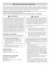
AssemMe LP Cooktop Orifices, Place in cooktop exactly as
layed out in the cover ofthB manual (also shown in Figure 3).
If the orifices become separated from the cover, placement
can be determined by matching the number stamped into the
orifice with the placement specifications displayed in Figure 4.
Place the new orifice into the socket then insert each orifice
into its respective threaded hole in the jet holder. Tighten until
the orifice stops turning. DO NOT OVERTIGHTEN.
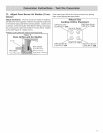
Figure 1
Convert Pressure Regulator
Pin Position
for Propane
I
Pin \
Position
Gas
PRESSUREREGULATORVIEW
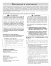
Figure 2
Remove Grate, Cap and Base
Burner Cap_ d:
Burner Base--_)
Orifice
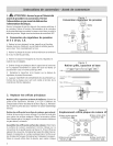
Figure 3
LP Cooktop Orifice Placement
Left Rear Burner : Right Rear Burner :
! 1,000 BTUIh 101 5,000 BTU/h 70
Left Front B_N T 6_
Right Front Burner -
7,500 BTU/h 86 !5,000 BTUih I:_B