STEP7 (continued)
INSTALLINGTHE COOKTOP
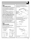
NOTE: If the cooktop is installed in a 36" base
cabinet, the mounting brackets cannot be used
because of the interference with the sides of the
cabinet. In this case, the cooktop can be secured
to the sides of the cabinet using angle brackets
(not supplied). Remove one screw at the bottom
of the cooktop body, on each side, then replace
to hold the bracket to the cooktop. Then secure
the brackets to the cabinet sides with the screws
provided.
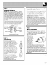
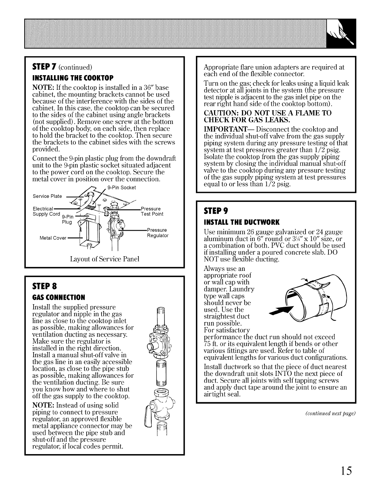
Connect the 9-pin plastic plug from the downdraft
unit to the 9-pin plastic socket situated adjacent
to the power cord on the cooktop. Secure the
metal cover in position over the connection.
9-Pin Socket
Service Plate
Electrical
Supply Cord 9-Pinplug"_ _--_-_1;
Metal Cover "_-!_
Layout of Service Panel
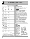
Pressure
Test Point
,Pressure
Regulator
STEP8
GASCONNECTION
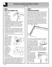
Install the supplied pressure
regulator and nipple in the gas
line as close to the cooktop inlet
as possible, making allowances for
ventilation ducting as necessary.
Make sure the regulator is
installed in the right direction.
Install a manual shut-off valve in
the gas line in an easily accessible
location, as close to the pipe stub
as possible, making allowances for
the ventilation ducting. Be sure
you know how and where to shut
off the gas supply to the cooktop.
NOTE: Instead of using solid
piping to connect to pressure
regulator, an approved flexible
metal appliance connector may be
used between the pipe stub and
shut-off and the pressure
regulator, if local codes permit.
Appropriate flare union adapters are required at
each end of the flexible connector.
Turn on the gas; check for leaks using a liquid leak
detector at all joints in the system (the pressure
test nipple is adjacent to the gas inlet pipe on the
rear right hand side of the cooktop bottom).
CAUTION: DO NOT USE A FLAME TO
CHECK FOR GAS LEAKS.
IMPORTANT-- Disconnect the cooktop and
the individual shut-off valve from the gas supply
piping system during any pressure testing of that
system at test pressures greater than 1/2 psig.
Isolate the cooktop from the gas supply piping
system by dosing the individual manual shut-off
valve to the cooktop during any pressure testing
of the gas supply piping system at test pressures
equal to or less than 1/2 psig.
STEP9
INSTALLTHE DUCTWORK
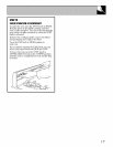
Use minimum 26 gauge galvanized or 24 gauge
aluminum duct in 6" round or 31/4"x 10" size, or
a combination of both. PVC duct should be used
if installing under a poured concrete slab. DO
NOT use flexible ducting.
Always use an
appropriate roof
or wall cap with
damper. Laundry
type wall caps
should never be
used. Use the
straightest duct
run possible.
For satisfactory
performance the duct run should not exceed
75 ft. or its equivalent length if bends or other
various fittings are used. Refer to table of
equivalent lengths for various duct configurations.
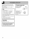
Install ductwork so that the piece of duct nearest
the downdraft unit slots INTO the next piece of
duct. Secure all joints with self tapping screws
and apply duct tape around the joint to ensure an
airtight seal.
(continued next page)
15


