


5
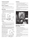
DRAWER ASSEMBLY
1. Pull out drawer until it stops.
2. Lift drawer slightly, then pull out drawer to second stop.
3. Lift drawer up and out of compactor.
FOOT PEDAL (MODELS 1050 & 1051 ONLY)
1. Remove foot pedal retainers from each side of pedal.
2. Push foot pedal hinge pin out, catch foot pedal spring as it
comes free.
DOOR LINER
Remove the door from the drawer by unlatching the door and
removing the hinge pins. The door liner can be removed from the
door by removing the toe space cover and all screws holding the
door liner to the door. Slide the door liner to side of door and lift
off. (Models 1050 and 1051 will require removal of the foot pedal
prior to toe space cover.)
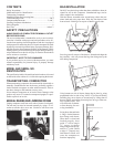
DRAWER AND BASE ROLLERS
All four of the rollers are secured with a 1/2" hex nut and slotted
for screwdriver. Roller nuts are installed using Locktite
R
and
torqued to 20 foot pounds. Rollers are pregreased and should
require no lubricant.
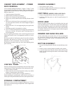
BOTTOM ASSEMBLY
1. Unscrew level legs from base. Remove tee nuts that legs screw
into.
2. Remove screws securing bottom assembly to the cabinet.
3. Lower the bottom down into the cabinet, back end first, then
bring it up and out through the notches in the bottom flange
of the cabinet.
CABINET REPLACEMENT - POWER
PACK REMOVAL
A box or similar stand approximately 11” high x 15” long x 7” wide
is recommended for power pack removal. The box must be able to
support 60 lbs. or more since you will be placing the full weight of
the power pack on it.
1. Unplug compactor from socket.
2. Remove drawer assembly from cabinet.
3. Remove Air Scentry tray and control panel.
4. Remove key switch control bracket assembly. Remove back
panel.
5. Place box in cabinet and lower ram manually by turning 15/
16" nut on sprocket clockwise. Box should support weight of
power pack.
6. Remove the four 5/16" nuts supporting the power pack in the
cabinet.
7. Disconnect ground wire attached to cabinet.
8. Turn 15/16" nut counterclockwise causing power pack to lower
down out of cabinet. Pull power pack out through front of
rear of compactor.
If you are replacing the cabinet, remove remaining parts from old
cabinet and install on new. See appropriate sections of service
manual.
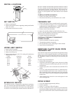
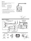
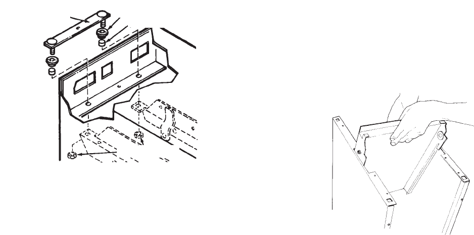
Reverse procedure to install power pack. Be sure the weld strip,
grommets, and spacers are in place. The lock nuts should be
torqued to 5 ft./lbs. (60 inch/lbs.). Do not overtorque.
Be careful not to pinch or nick any wires when installing power
pack in cabinet.
CONTROL PANEL
On units with a bag storage compartment, removal of the storage
compartment will make replacement of the control panel easier.
1. Remove drawer assembly.
2. Remove the four screws securing the air scentry tray and the
bottom of control panel to the cabinet.
3. Pull bottom of control panel out slightly and then up.
When installing the control panel, make sure lip on inside of
control panel snaps behind the bend in the control panel bracket.
STORAGE COMPARTMENT
Remove two screws on rear of compactor and the two 5/16" hex
head screws inside the storage compartment. Slide compartment
back and lift off.
WELD STRIP
GROMMETS
SPACERS
LOCK NUTS
POWER PACK
MOUNTING