


PLANNING - (continued)
Note: The high level of air flow of this appliance may affect the gas
flame on some types of gas cooktops. This is NORMAL and will
cause no harm, but can be corrected by lowering the speed of the
blower.
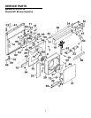
Pay special attention to the areas of potential interference high-
lighted above. A countertop with (A) a raised lip and/or (B) a
backsplash may not allow enough flat countertop for a proper
installation. Note that 2" of flat countertop is required behind
cooktop and that 1-3/4" is necessary between the back edge of the
cooktop and the inside of cabinet back.
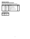
SPECIFICATIONS
VOLTS AMPS CFM DUCT
120 4.0 500 3-1/4 x 10
PLAN THE DUCTWORK
2
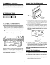
TAKE MEASUREMENTS
1. Refer to the cooktop installation instructions for dimensions of
cooktop, countertop cut-out, and cabinet requirements. The
Model 2730 will fit in most 30" wide cabinets and the Model
2736 will fit in most 36" wide cabinets. However, it is recom-
mended that oversized cabinets be used for easier installa-
tion.
2. Cooktop depth can vary greatly from one to another. This may
cause the fit of these two appliances to be rather tight.
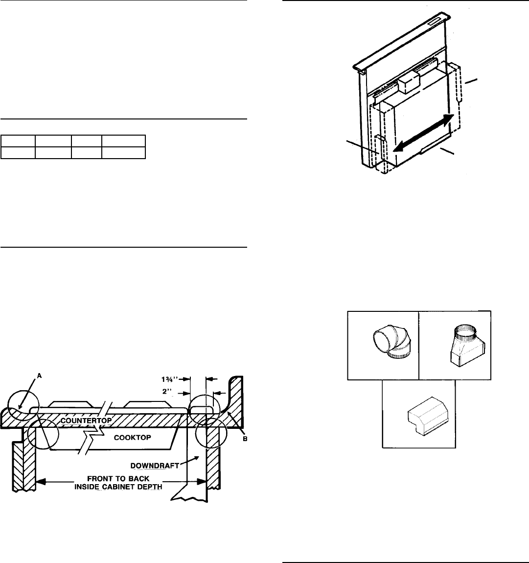
3. The system will operate most efficiently when the ductwork
does not exceed 40 feet of equivalent duct. The chart, above,
shows equivalent feet of elbows and transitions. The number
of feet of straight duct plus the equivalent feet of transitions
and/or elbows to be used should equal 40 feet or less.
NOTE: The equivalent feet of various roof and wall caps has
been taken into consideration. Do not include them in this
calculation.
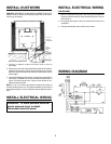
PLAN THE WIRING
1. The downdraft and exterior blower system draws 4 AMPS and
requires a 120 VAC, 60 Hz circuit.
2. Plan to provide unit with grounded wiring which meets codes:
Note: Installations in which the fit between blower system and
cabinet is tight.
Consider running the wiring through a adjacent
cabinet to prevent sharp bends in wiring.
EQUALS 6 FT. OF
STRAIGHT DUCT
8" ROUND
ELBOW
3-1/4" X 10"
TO 6" RD.
TRANSITION
3-1/4" X 10"
90
O
ELBOW
EQUALS 8
FT. OF
STRAIGHT DUCT
EQUALS 2
FT. OF
STRAIGHT DUCT
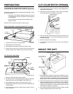
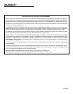
1. This downdraft blower system is designed for use with 3" x
10" ductwork (can be transitioned to 6" round). Three different
discharge directions are available with side-to-side adjust-
ment for accurate alignment of ductwork.
2. For best performance: Choose the ducting option which allows
the shortest length of ductwork and a minimum number of
elbows and transitions. Check location of floor joists, wall
studs, electrical wiring or plumbing for possible interference.
NOTE: The unit is shipped with the 3" x 10" discharge facing
DOWN. See "CHANGING BLOWER DIRECTION" on page 3,
if necessary.
RIGHT
DISCHARGE
DOWN'
DISCHARGE
(as shipped)
LEFT
DISCHARGE