


INSTALL THE
DUCTWORK
For Ducted Installations Only:
NOTE
THESE INSTRUCTIONS WILL FOLLOW THE
PLANS MADE ON PAGE 2. START ON THE
OUTSIDE AND WORK BACK TOWARD
HOOD. FOLLOW APPROPRIATE DIREC-
TIONS FOR TYPE OF DUCT SYSTEM YOU
ARE INSTALLING.
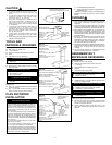
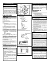
WALL CAPS (FIG. 6)
Use a saber saw to cut a hole slightly larger than
duct so duct will line up easily with hood. Install
casing strips on outside walls finished in siding.
Assemble the ductwork and tape all joints. Run
ductwork back to hood. Fasten wall cap to last
section of duct and nail or screw cap to wall. Seal
all around flange on wall cap with caulking com-
pound. Make sure that enough duct runs into the
room so that the duct will overlap the damper/duct
connector by 3/4” when the hood is installed.
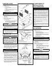
ROOF CAPS (FIG. 7)
Cut hole in roof slightly larger than duct so duct
will line up easily with hood. Trim shingles around
hole so that they will fit snugly around hood of cap
when cap is installed. Assemble the ductwork and
tape all joints. Run the ductwork down to hood.
Trim duct parallel to roof pitch, leaving 3/4” of duct
projecting above roof (FIG. 7A). Seal all around
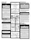
duct with roof cement. (FIG 7B) Install roof cap,
inserting back edge of cap under shingles. (FIG
7C) Seal around roof cap with roof cement and
seal all nail heads and shingles which were cut or
lifted. (FIG. 7D)
Make sure that enough duct runs into the room so
that the duct will overlap the damper/duct connec-
tor by 3/4” when the hood is put into place.
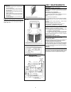
INSTALL HOOD
1. Position hood so that: (FIG. 8)
a.) electrical wiring runs through opening in top
or back of hood.
b.) large part of keyhole slots fit over hood mount-
ing screws
For Ducted Installations Only:
c.) damper/duct connector slides into ductwork.
2. Push hood back so that mounting screws slide
into narrow end of keyhole slots. When mounting
larger hoods, run (2) screws through the 1/4” dia.
holes (in hood top and 8” each side of center)
and into the cabinet bottom or added filler strips.
Tighten all screws firmly.
3. Install locknut on electrical connector and tighten
securely.
4. Make electrical connections. Connect white to
white, black to black, and green or bare wire to
green ground screw. (FIG. 9)
5. Replace wiring box cover and screws. Make sure
that wires are not pinched between cover and
hood.
6. Install two 75 watt max. bulbs, or one 75 watt bulb
and one 25 watt bulb for night-light use. Install 25
watt bulb in righthand socket.
For Ducted Installations Only:
Reinstall blower. Do not grasp blower by blower
wheels. Position blower so that blower discharge
lines up with damper/duct connector and slip rods
into mounting brackets on blower assembly. (FIG.
10) Tighten knurled nuts securely, and plug in
blower.
For Ductfree Installations Only:
1. Reinstall blower. Do not grasp blower by
blower wheels. Move blower mounting rods
to front holes in hood support channels. (FIG.
11) Position blower so that blower discharge
lines up with louvered opening on hood front.
2. Slip rods into mounting brackets and tighten
knurled nuts securely. Plug in blower.
3. Remove louver cover on control panel. Pry
cover off with screwdriver or knife.
7. Reinstall bottom cover and screws. (FIG. 2)
FIG. 5
FIG. 6*
FIG. 7B*
FIG. 7A*
PREPARANDO EL
LUGAR DE INSTALACION
NOTA
SI LA DISTANCIA ENTRE LA PARED Y EL FRENTE
DEL MARCO DEL GABINETE ES MAS DE 30,48 CM
(12 PULG.) HABRA UN ESPACIO VACIO ENTRE LA
PARTE DE ATRAS DE LA CAPUCHA Y LA PARED.
ESTO ES NORMAL. EL BORDE FRONTAL SUPE-
RIOR DE LA CAPUCHA DEBE ESTAR A NIVEL CON
EL FRENTE DEL MARCO DEL GABINETE. OMITA
PASO 1 SI LA CAPUCHA SE VA A INSTALAR BAJO
GABINETES CON FONDO A NIVEL CON EL MARCO.
1. SOLAMENTE para gabinetes con fondo que no está a
nivel con el marco: (FIG. 4)
Instale las tiras de madera para relleno en cada lado del
área que no está a nivel con el marco bajo el gabinete.
Use dos tiras de 2,54 cm X 5,08 cm (1 X 2 pulg.) del
tamaño apropiado (use tiras más gruesas si es
necesario). Fije las tiras con tornillos para madera como
a 7,62 cm (3 pulg.) de cada extremo.
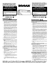
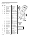
2. Mida y marque lo siguiente: (FIG. 5)
a) abertura para cableado eléctrico
Solamente para instalaciones con conductos
b) abertura del conducto
3. Haga la abertura del conducto en la pared o al fondo
del gabinete
4. Taladre una abertura de 3,18 cm (1-1/4 pulg.) para
cableado eléctrico en la pared o al fondo del gabinete.
5. Sostenga la capucha contra el fondo del gabinete y trace
ranuras como ojo de llave en el fondo del gabinete o en
las tiras de relleno. Para capuchas más grandes: se
suministran dos agujeros de 0,64 cm (1/4 pulg.) de
diámetro para una instalación segura. Están en la parte
superior de la capucha aproximadamente 20,32 cm (8
pulg.) a cada lado del centro. Agregue tiras de relleno
para estos según sea necesario. Evite taparle a la
capucha el disco removible vertical para lo eléctrico.
6. Atornille cuatro tornillos para madera de 2,22 cm (7/8
pulg.) de la bolsa de piezas exactamente en el centro
del extremo angosto de la figura como ojo de llave que
se trazó en el fondo del gabinete. Deje 0,95 cm (3/8
pulg.) de los tornillos sin atornillar para montar la capucha
en su lugar más tarde.
7. Pase cableado eléctrico por el agujero que se taladró
en la pared o gabinete. Deje 15,24 cm (6 pulg.) de cable
e instale el conector apropiado para el tipo de cable que
se usa.
INSTALANDO
LOS CONDUCTOS
Solamente para instalaciones con conductos:
NOTA
ESTAS INSTRUCCIONES SIGUEN LA
PLANIFICACIÓN QUE SE HIZO EN PÁGINA 3.
EMPIECE POR EL EXTERIOR Y TRABAJE
HACIA LA CAPUCHA. SIGA LAS DIRECCIONES
APROPIADAS PARA EL SISTEMA DE
CONDUCTOS QUE USTED ESTA INSTALANDO.
TAPAS PARA PARED (FIG. 6)
Use una sierra de hoja para cortar un agujero un poco
más grande que el conducto para que éste se alinee
fácilmente con la capucha. Instale tiras de contramarco
en las paredes exteriores que tienen acabado en
chapas de forrado. Arme los conductos y forre todas
las uniones con cinta. Instale conductos hasta la
capucha. Fije la tapa para pared a la última sección
del conducto y clave o atornille la tapa a la pared. Selle
bien alrededor del borde de la tapa en la pared con
masilla de calafateo. Verifique que haya suficiente
conducto dentro de la habitación para que éste calce
sobre la unión del amortiguador/conducto con un borde
de 1,91 cm (3/4 pulg.) cuando se instale la capucha.
TAPAS PARA TECHO (FIG. 7)
Haga un agujero en el techo un poco más grande que
el conducto para que éste se alinee bien con la
capucha. Recorte las chapas alrededor del agujero
para que calcen de una manera compacta con la
capucha de la tapa cuando ésta se instale. Arme los
conductos y forre todas las uniones con cinta. Lleve
los conductos hasta la capucha. Recórtelos de una
forma paralela a la inclinación del techo, dejando 1,91
cm (3/4 pulg.) de conducto por encima del techo (FIG.
7A). Selle todo alrededor del conducto con cemento
para techo. (FIG. 7B). Instale la tapa para techo,
FRONT OF CABINET FRENTE DEL GABINETE
1/8"
0,32
CM
HORIZONTAL DUCT OPENING*
ABERTURA CONDUCTO HORIZONTAL*
3–7/8"
9,84
CM
3/4"
1,90 CM
* FOR DUCTED INSTALLATIONS ONLY.
* SOLAMENTE PARA INSTALACIONES CON CONDUCTOS.
VERTICAL DUCT OPENING*
ABERTURA CONDUCTO VERTICAL*
CABINET BOTTOM FONDO DEL
CABINETE
BACK WALL PARED TRASERA
9" 22,86 CM
9" 22,86 CM
10-5/8"
26,99
CM
6-7/
8"
17,46
CM
6–1/4"
15,87 CM
6–1/4"
15,87 CM
7–1/2"
19,05 CM
9–7/8"
25,08
CM
* FOR DUCTED INSTALLATIONS ONLY.
* SOLAMENTE PARA INSTALACIONES CON CONDUCTOS.
FIG. 8
* FOR DUCTED INSTALLATIONS
ONLY.
* SOLAMENTE PARA
INSTALACIONES CON
CONDUCTOS.
PLASTIC ROOF
CEMENT
CEMENTO PLASTICO
PARA TECHO
3/4"
1,91 CM
(3/4
PULG.)
* FOR DUCTED INSTALLATIONS
ONLY.
* SOLAMENTE PARA
INSTALACIONES CON
CONDUCTOS.
* FOR DUCTED INSTALLATIONS
ONLY.
* SOLAMENTE PARA
INSTALACIONES CON
CONDUCTOS.
FIG. 7C* FIG. 7D*
DO NOT CAULK AROUND
BOTTOM OF FLANGE FOR
DRAINAGE
NO PONGA MASILLA ALREDEDOR
DE LA PARTE INFERIOR DEL
BORDE PARA DRENAJE
NAIL
CLAVO
* FOR DUCTED INSTALLATIONS
ONLY.
* SOLAMENTE PARA
INSTALACIONES CON
CONDUCTOS.
3/8"
0,95 CM
6–1/4"
15,87 CM
6–1/4"
15,87 CM
7–1/2"
19,05 CM
1–1/2"
3,81 CM
1–1/2"
3,81 CM
ELECTRICAL LINE
LINEA ELECTRICA
4