


APE1 SERIES
Page 2
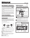
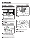
CLEANING & MAINTENANCE
For performance, appearance, and health reasons, clean filter,
fan and grease-laden surfaces. Use only a clean cloth and mild
detergent solution on stainless and painted surfaces. Clean all-
metal filters in the dishwasher.
The motor is permanently lubricated and never needs oiling. If
the motor bearings make excessive or unusual noise, replace
the motor with the exact service motor. The impeller should also
be replaced.
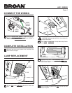
Use 120 V, 42 W fluorescent lamp GX24Q-4. For night light, use
4 W, C-7 bulbs. (Bulbs included with hood.)
The grease filters, bottom panel, and blower wheel should be
cleaned frequently. Use a warm detergent solution. The grease
filters and blower wheel are dishwasher safe.
Note: Some minerals, when in contact with dishwasher soap
additives, may cause filters to discolor. This discoloration is not
covered by the warranty.
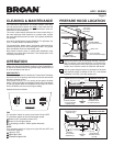
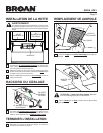
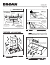
PREPARE HOOD LOCATION
SOFFIT
18" - 24" ABOVE
COOKING SURFACE
CABINET
3¼" X 10" DUCT
(For horizontal discharge)
WALL CAP
ROOF CAP
3¼" X 10"
(For vertical
discharge)
HOUSE WIRING
(Top or Back of hood)
HOODHOOD
1 Determine whether hood will discharge vertically or horizon-
tally. For vertical or horizontal discharge, run ductwork be-
tween the hood location and a roof cap or wall cap. For best
results, use a minimum number of transitions and elbows.
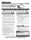
OPERATION
Always turn the hood ON before cooking in order to establish an
air flow in the kitchen. After turning off the range, let the hood run
for a few minutes to clear the air.
HEAT SENTRY™
The hood is equipped with a Heat Sentry™ thermostat. This safety
device will turn on or speed up the blower if it senses excess heat
above the cooking surface.
If the blower is not on, or if it is running at low speed, the Heat
Sentry™ will override the normal blower control and run the blower
on the high speed. When the temperature level drops to normal
levels, the blower will return to its original setting.
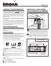
Operate the hood as follows:
FAN
The 2-position switch (in center) turns blower ON and OFF.
The 5-position switch (at left) controls blower speed.
Blower is OFF (secondary blower OFF).
Blower is ON at highest speed.
As dots get smaller - blower speed decreases.
LIGHT
This 3-position switch (at right) turns lights ON and OFF and
controls their intensity.
Lights are OFF.
Night Light is ON.
Fluorescent Light is ON.
LIGHTFAN
FAN
ON OFF
CABINET
BOTTOM
CABINET FRONT
HORIZONTAL DUCT
ACCESS HOLE
6¼"
6¼"
3
/
4
"
HOOD
MOUNTING
SCREWS (4)
ELECTRICAL
ACCESS HOLE
(in wall)
3
7
/
8
"
CENTER
LINE
WOOD SHIMS
(recessed-bottom
cabinets only)
7
1
/
2
"
1
/
8
"
16
15
/16" (36" hood)
16
15
/16" (36" hood)
13
15
/16" (30" hood)
13
15
/16" (30" hood)
9"
CENTER
LINE
HOOD MOUNTING SCREWS (4)
ELECTRICAL
ACCESS HOLE
(in cabinet bottom)
WOOD SHIMS
(recessed-bottom
cabinets only)
CABINET FRONT
CABINET
BOTTOM
16
15
/16" (36" hood)
16
15
/16" (36" hood)
13
15
/16" (30" hood)
13
15
/16"
(30" hood)
1
1
/
2
"
7
1
/
2
"
VERTICAL DUCT
ACCESS HOLE
6¼"
6¼"
10
5
/
8
"
6
7
/
8
"
9
7
/
8
"
3¼” X 10”
VERTICAL DUCTING
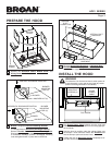
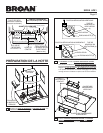
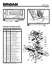
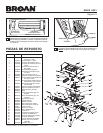
2 Use the proper diagram below, for placement of ductwork
and electrical cutout in cabinet or wall. For a non-ducted
installation, DO NOT cut a duct access hole.
3¼” X 10”
VERTICAL DUCTING