


- 5 -
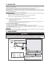
2. PREPARE THE INSTALLATION (CONT’D)
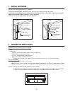
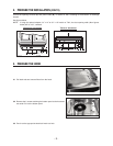
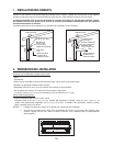
Cut-out the openings for duct (A) and power cable (B), in cabinet or wall, according to the direction of discharge
chosen.
See figures below.
NOTE: If using the optional adaptor 3¼” x 14” to 3¼” x 10” model no. T461, the duct opening width (A on figures
below) will be 10½”, centered.
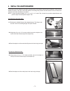
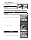
3.1 Pull latch tabs and remove filters from the hood.
C
L
HD0121A
3½”
7¼” 7¼”
2¾”
B
1½” dia.
A
7
8
”
3. PREPARE THE HOOD
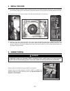
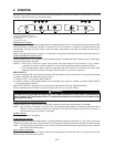
3.2 Remove the 5 screws retaining the bottom panel to the hood and
set aside. Pull out the bottom panel.
HO0030
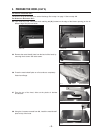
3.3 Punch out the appropriate electrical knock-out hole.
C
L
7/8’’
4¼’’
7¼’’ 7¼’’
2’’
HD0120A
A
CABINET BOTTOM
1³ ’’
8
2’’
1½’’
B
HORIZONTAL DISCHARGE
VERTICAL DISCHARGE
HD0107
SCREW
LOCATIONS