Page 17
SERVICE (cont.)
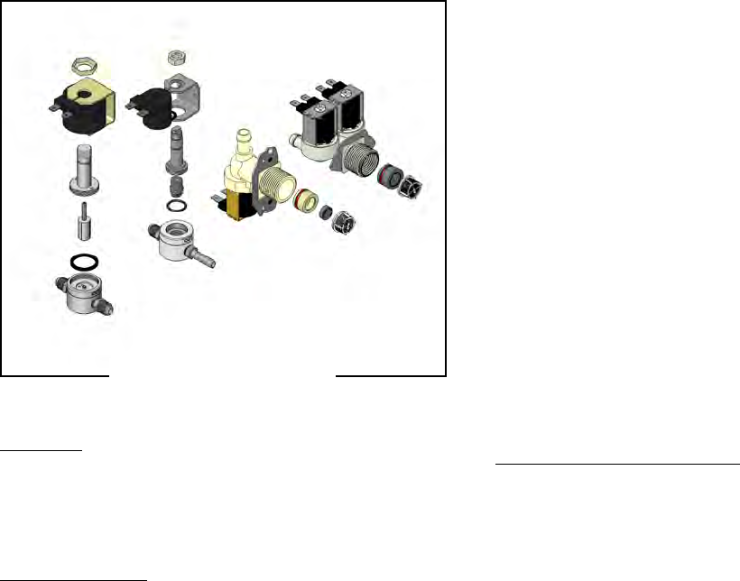
INLET VALVES
Location:
The solenoid valve(s) are located inside the trunk
on the lower center part of the component bracket. So-
lenoids in the early models are located in the hood.
Test Procedures:
1. Check the solenoid valve for coil action. With "ON/
OFF" switch in the "ON' upper position press start
switch and listen carefully in the vicinity of the
solenoid valve for a" clicking" sound as the coil
magnet attracts.
2. Disconnect the brewer from the power source.
If the sound is heard as described and water will not
pass through the solenoid valve, there may be a block-
age in the water line before the solenoid valve or, the
solenoid valve may require inspection for wear, and
removal of waterborne particles.
If the sound is not heard as described, proceed to
#3.
3. Disconnect the brewer from the power source.
4. Connect a voltmeter across the solenoid terminals
(leave wires connected).
5. Connect the brewer to the power source. With the
"ON/OFF" switch in the "ON" upper position press
the start switch.
6. Check the voltage across the solenoid. The indica-
tion must be:
a) 120 volts ac for two wire 120 volt models and
three wire 120/240 volt models.
b) 200 to 230 volts ac for two wire 200 or 230 volt
models.
7. Disconnect the brewer from the power source,
If voltage is present as described, proceed to #8
If voltage is not present as described, refer to Wiring
Diagrams and check brewer wiring harness.
8. Check for continuity across the solenoid termi-
nals.
If continuity is present as described, reconnect the
white and black wire from the timer.
If continuity is not present as described, replace the
solenoid valve.
Removal and Replacement:
1. Disconnect the brewer from the power source.
2. Turn off the water supply to the brewer.
3. Remove the wires from the solenoid.
4. Disconnect the water lines to and from the solenoid
valve.
5. Remove the two screws securing the solenoid
mounting bracket to the component bracket.
6. Install new solenoid valve to the component
bracket.
7. Securely fasten the water lines to and from the
solenoid valve.
8. Refer to schematics when reconnecting the
wires.
FIG. 17-1 INLET VALVES
41722 070209


