Page 20
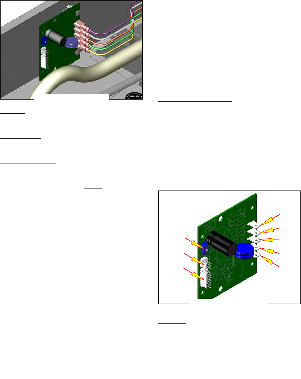
FIG. 20-1 DIGITAL TIMER
FIG. 20-2 DIGITAL TIMER
DIGITAL BREW TIMER (TB3Q & TB6Q)
SERVICE (cont.)
Location:
The timer is located in left side of the hood.
Test Procedure
NOTE: Do not remove or install wires while timer board
is installed. Pressure applied to one side may cause
damage to the board.
1. Disconnect the brewer from the power source and
remove the top cover.
2. With a voltmeter, check the supply voltage across
terminals TL1 and TL2. Connect the brewer to the
power source. Turn on the "ON/OFF" switch. The
voltage must be:
a) 120 volts ac for two wire 120 volt models.
b) 200 to 230 volts ac on two wire 200 volt or
230 volt models.
3. Disconnect the brewer from the power source.
If voltage is present as described, proceed to #4.
If voltage is not present as described, refer to the Wir-
ing Diagrams and check the wiring harness.
4. With a voltmeter, check the output voltage across
terminals TL1 and TL4. Connect the brewer to the
power source, turn on the "ON/OFF" switch and
press the "START" switch. The voltage must be:
a) 120 volts ac for two wire 120 volt models.
b) 200 to 230 volts ac for two wire 200 volt or 230
volt models.
If voltage is present as described, the timer is operat-
ing properly. If voltage is not present as described,
proceed to #5.
5. With a voltmeter, check the input start voltage
across terminals TL2 and TL5. Connect the brewer
to the power source, turn on the "ON/OFF" switch
and press the "START" switch. The indication must
be as follows:
a) 120 volts ac for two wire 120 volt models.
b) 200 to 230 volts ac on two wire 200 volt or
230 volt models.
If voltage is not present as described, refer to the
Wiring Diagrams and check the wiring harness to the
start switch.
If start voltage is present as described (but no output
voltage), replace the timer.
Removal and Replacement:
1. Remove the two #6-32 screws, lock washers and
spacers securing timer to bracket.
2. Disconnect all wires from the timer.
3. Refer to schematic and reconnect wires.
4. Install new timer to bracket with the two #6-32
screws, lock washers and spacers.
5. Adjust the timer as required.
Terminals:
J-2 ½ batch connector
J-1 Multi batch (NOT USED IN TB SERIES)
SW-1 Programming Enable/Disable
TRM-1 White/Violet L1 from ON/OFF switch
TRM-2 White (Red) Neutral (L2)
TRM-3 White/Orange Start switch
TRM-4 White/Green Brew solenoid
TRM-5 White/Yellow Start switch
SW1
TRM-5
TRM-4
TRM-3
TRM-2
TRM-1
J-1
J-2
41722 070209


