


11
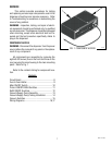
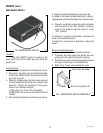
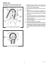
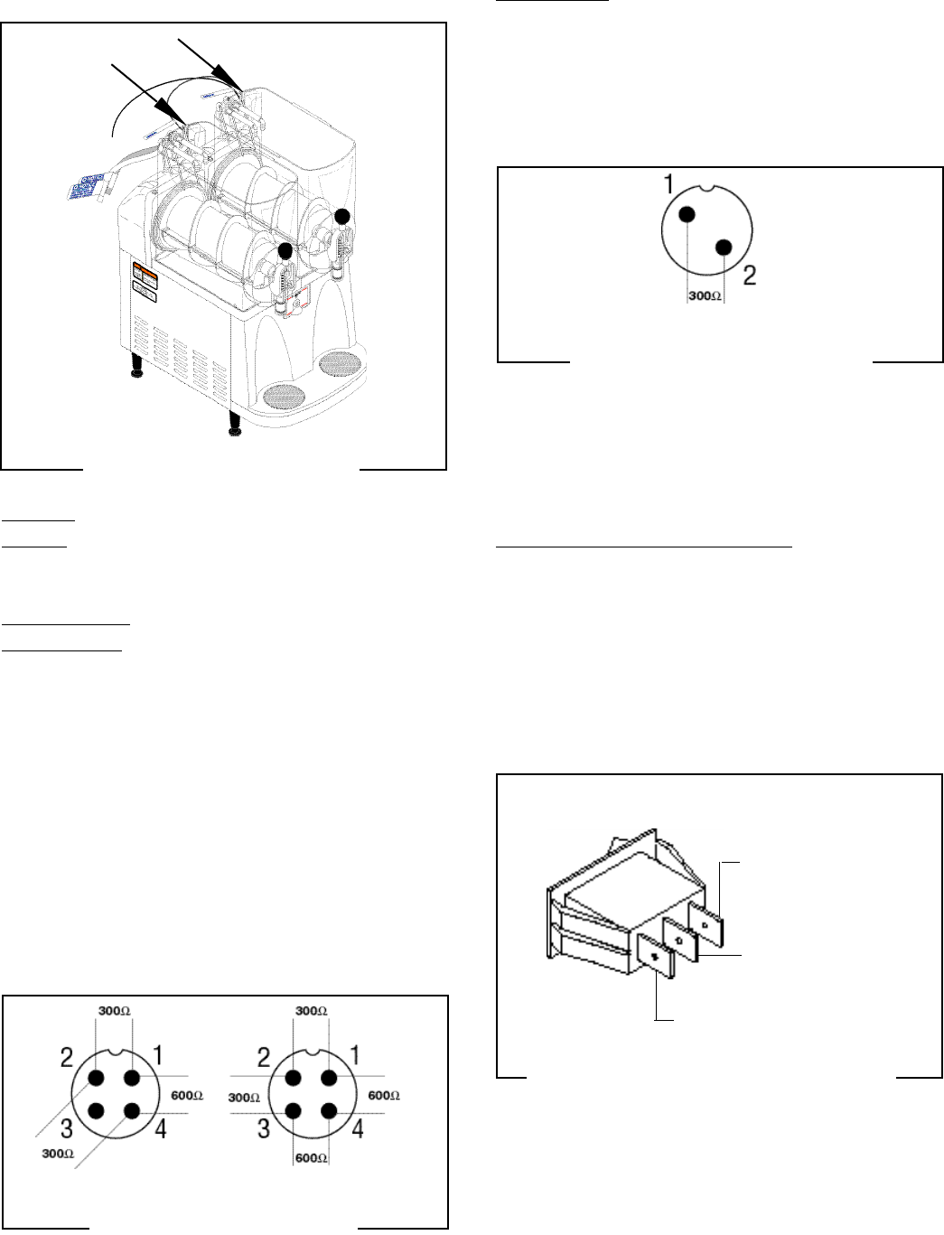
FIG. 8 PROBE SWITCHES
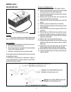
Probe Boxes:
1. Disconnect the signal cable from the probe boxes.
2. Remove probe box from CDS hopper.
3. Place the switch on the probe box in the “HIGH”
position.
4. Check the resistance across the box cable pins,
see Fig. 8B.
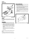
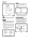
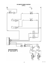
PROBE SYSTEM
P1523
P1539
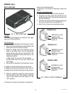
FIG. 8B PROBE BOX CABLE PINS
SERVICE (cont.)
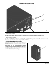
Location
The probe switches are located on the rear of
each hopper, mounted in the probe housing cover.
Test Procedure
Probe System
1. Disconnect the dispenser from the power source.
2. With the probe boxes connected to the signal
cable, remove connector from refill box.
3. Place the switch on the probe box in the “HIGH”
position.
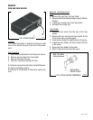
4. Check resistance across pins as shown in Fig 8A.
5. With the probe box switch in “LOW” position
check the ohms across the signal cable pins, see
Fig. 8A.
6. If readings match values indicated the probe
system electrically is functioning properly. If not
check the probe boxes.
5. With the probe box switch in the “LOW” position
check the ohms across the pins, refer to Fig. 8B.
6. If readings match the values indicated the probe
system electrically is functioning properly.
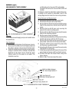
Switch Removal and Replacement:
1. Remove the #6 thread cutting screw securing the
probe housing cover to the probe housing.
2. Remove the wires from the switch terminals.
3. Compress the clips inside the probe box and gently
push the switch through the opening
4. Push the new switch into the opening and spread
the clips to hold switch in the autofill box.
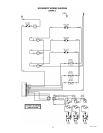
5. Refer to Fig 9 when reconnecting the wires.
FIG. 8A SIGNAL CABLE PINS
P1538
FIG. 9 PROBE LOW/OFF/HIGH SWITCH TER-
MINALS
P1540
BLU (HIGH) fromProbe
Box Cable
GRN (OFF) from Probe
Box Cable
TAN (LOW) from Probe Box
Cable
28791.1 011500
AFPR-2
AFPR-3
AFPR-2 & 3