


13
G
R
N
P
U
M
P
#
1
P
U
M
P
#
2
1
0
A
M
P
M
A
I
N
O
N
/
O
F
F
S
W
I
T
C
H
R
E
F
I
L
L
O
N
/
O
F
F
S
W
I
T
C
H
#
1
R
E
F
I
L
L
O
N
/
O
F
F
S
W
I
T
C
H
#
3
R
E
F
I
L
L
O
N
/
O
F
F
S
W
I
T
C
H
#
2
J
4
-
1
2
3
4
5
6
7
8
9
J
4
-
1
0
C
I
R
C
U
I
T
B
O
A
R
D
L
1
N
B
L
K
B
L
K
B
L
K
B
R
N
/
B
L
K
B
L
K
R
E
D
/
B
L
K
R
E
D
/
B
L
K
B
L
K
O
R
N
O
R
N
O
R
N
V
A
C
U
U
M
S
W
I
T
C
H
#
2
V
A
C
U
U
M
S
W
I
T
C
H
#
3
V
A
C
U
U
M
S
W
I
T
C
H
#
1
B
R
N
/
B
L
K
W
H
I
W
H
I
W
H
I
W
H
I
W
H
I
P
U
M
P
#
3
R
E
D
W
H
I
W
H
I
V
I
O
Y
E
L
Y
E
L
Y
E
L
S
C
H
E
M
A
T
I
C
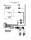
W
I
R
I
NG
D
I
A
G
R
A
M
AF
P
R
-
3
1
4
2
3
1
4
2
3
G
R
N
G
R
N
G
R
N
G
R
N
R
E
D
B
L
K
B
L
K
B
L
K
B
L
K
B
L
K
B
L
K
1
2
1
2
1
2
1
2
L
H
L
H
P
R
O
B
E
C
O
N
T
R
O
L
1
P
R
O
B
E
C
O
N
T
R
O
L
2
1
2
1
2
LH
P
R
O
B
E
C
O
N
T
R
O
L
3
1
2
0
V
O
L
T
A
C
2
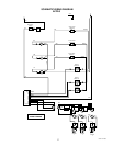
W
I
R
E
S
I
N
G
L
E
P
H
A
S
E
2
8
8
1
4
.
0
0
0
3
E
7
/
9
8
©
1
9
9
8
B
U
N
N
-
O
-
M
A
T
I
C
C
O
R
P
O
R
A
T
I
O
N
W
H
I
/
R
E
D
R
E
D
W
H
I
/
R
E
D
G
R
Y
T
A
N
T
A
N
T
A
N
B
L
U
B
L
U
B
L
U
1
2
1
2
FLA
FLA
VOR
OR
INPUT
INPUT
MIXED PR
MIXED PR
ODUCT OUTPUT
ODUCT OUTPUT
2
1
1
2
3
3
3
WATER
TER
INP
UT
INPUT
REFILL
REFILL
MAIN
MAIN
PO
PO
WER
WER
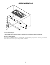
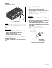
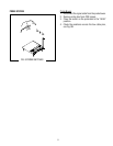
SERVICE (cont.)
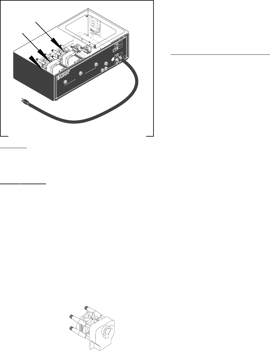
VACUUM/SUPPLY PUMP ASSEMBLY
FIG. 16 VACUUM/SUPPLY PUMP ASSEMBLY
P1560
Location:
The vacuum/supply pumps are located inside
the autofill box.
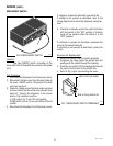
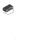
Test Procedure:
1. Disconnect the dispenser from the power source.
2. Disconnect the white wire from the pump lead and
the yellow, orange or red wire from the other lead.
3. Check the voltage across the white wire and yel-
low, orange or red wire with a voltmeter. Connect
the dispenser to the power source. Push the pump
(flavor) switch for the pump to be tested. The
indication must be :
a) 120 volts ac for two wire 120 volt models.
b) 200 to 240 volts ac for two wire 200 or 240 volt
models.
If voltage is present as described, replace the pump.
If voltage is not present as described, refer to the
wiring diagrams and check the main wiring harness.
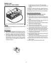
Pump Removal and Replacement:
1. Disconnect the wires from the pump leads.
2. Disconnect the input and output tubes.
3. Remove the four thumb screws securing the pump
head to the pump body, discard pump head with
tubes.
4. Remove the two #8-32 keps nuts securing the
pump to the main mounting panel.
5. Remove the two #6-32 screws securing the pump
body to the mounting bracket.
6. Remove pump body and discard.
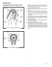
7. Install new pump assembly on the pump mount-
ing bracket and secure with two #6-32 screws.
8. Remove the four thumb screws securing the new
pump head with hoses to the new pump body.
9. Using two #6-32 screws mount the pump body on
the pump mounting bracket.
10. Using two #8-32 keps nuts mount the pump body
and bracket to main panel.
11. Install new pump head with hoses to the rear of the
pump body and secure with four thumb screws.
12. Connect the input and output tubes using new
hose clamps.
13. Refer to Fig 17 and reconnect the wires.