


3
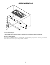
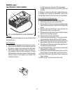
INITIAL SET-UP
NOTE: This refill unit should not be used to initially fill the hopper. Running the motor for extended periods will
trip the thermal switch. The thermal switch will reset, but requires up to 30 minutes of cooling time.
NOTE: Hoses, clamps and product container connectors are not supplied. Fittings and labels are supplied. Make
hose assemblies as required.
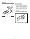
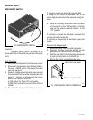
1. Assemble hoppers with probe housing assemblies to CDS-2, CDS-3 or modify existing hoppers using template
provided.
2. Make sure probe housing assembly is pushed down into slots on back of hoppers.
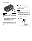
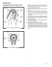
3. Install cable assembly to the lower right front of the auto refill box and the probe housing assemblies on the
hoppers. The connectors on the cable pushes in and cap rotates 1/4 turn to lock into position.
4. Run output tubes from auto refill box to the quick disconnects in the hoppers.
NOTE: Make sure numbers on the labels match up. Cable#1 with Hose#1, Cable#2 with Hose#2...ect.
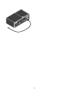
5. Connect one end of input hoses to the auto refill box and the other end to the product container. Product
container connectors (BIB) are not supplied. Install your own interface.
NOTE: Make sure all connections are made before connecting the auto refill box to the power source.
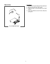
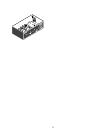
6. Each product container has an ON/OFF refill switch located on the front of the auto refill box. A second switch
for each hopper is at the probe housing assembly. These are 3 position switches, high level, low level and a
center “OFF” position.
7. Place the main ON/OFF switch and ON/OFF refill switches in the “OFF” position.
8. Make sure all hoses are connected. Connect the dispenser to the power source and place the main ON/OFF
switch in the “ON” position.
9. Place one of the ON/OFF refill switches in the “ON” position, after a four second delay product will begin to
flow through the hoses into the hopper. Be sure the switch selected is filling the correct hopper, if not, check
the labels. See NOTE in step #4.
10. To test refill circuit short out probes on one of the hoppers with a screwdriver, that hopper should shut off,
remove the screwdriver and the hopper will start to fill again after a four second delay. If hopper does not start
to fill, check labels, refer to NOTE in step #4.
ELECTRICAL REQUIREMENTS
CAUTION - The dispenser must be disconnected from the power source until specified in
Initial Set-Up.
The 120 volt version of this dispenser has an attached cordset and requires 2-wire, grounded service rated 120
volts ac, 15 amp, single phase, 60 Hz. The mating connector must be a NEMA 5-15R.
The 200 volt or 240 volt versions require 2 wire, grounded service rated 200 volts ac or 240 volts ac, single
phase, 50 Hz.
(
Refer to the dispenser’s data plate for exact voltage requirement.)
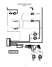
ELECTRICAL HOOK-UP
CAUTION – Improper electrical installation will damage electronic components.
1. An electrician must provide electrical service as specified.
2. Using a voltmeter, check the voltage and color coding of each conductor at the electrical source.
3. Connect the dispenser to the power source.
28791.1 011500