


18
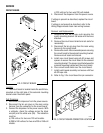
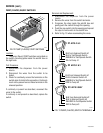
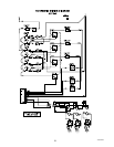
FLA
VO
R
IN
PU
T
1
2
W
A
T
E
R
IN
P
UT
R
EF
ILL
M
AIN
PO
W
E
R
2 1
1
2
3
3
3
FLA
V
O
R
O
UTP
UT
FLA
VO
R
O
U
TP
UT
W
A
T
ER
O
U
TP
UT
FLA
VO
R
O
UTP
U
T
W
A
T
ER
O
UTP
U
T
W
A
T
ER
O
UTP
U
T
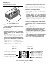
SERVICE (cont.)
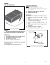
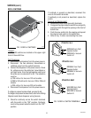
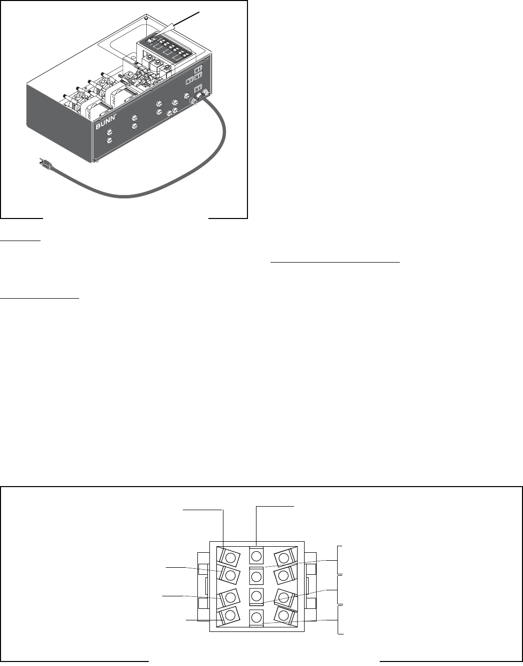
TEST/OPERATE ON/OFF SWITCH
FIG. 20 TEST/OPERATE SWITCH
Location
The test/operate switch is located inside the autofill
box on the right side.
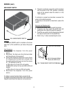
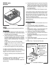
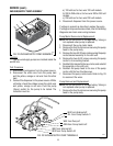
Test Procedures:
1. Disconnect the dispenser from the power source.
2. Remove the black wire from the top center switch
terminal.
3. Connect the dispenser to the power source. With a
voltmeter, check the voltage across the black wire
removed from the test/operate switch and the white
wire from one of the solenoids. The indication must
be:
a) 120 volts ac for two wire 120 volt models.
b) 200 to 240 volts ac for two wire 200 or 240 volt
models.
c) 230 volts ac for two wire 230 volt models.
P1521
5. Disconnect the dispenser from the power source.
If voltage is present as described, proceed to #6.
If voltage is not present as described, refer to the Wiring
Diagrams and check the wiring harness.
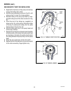
6. Disconnect the wires from the left and center
terminals.
7. Check for continuity across the left and center
terminals in rows one, two, three and four with the
switch in the “operate” position. Continuity should
not be present across the left and center terminals
with the switch in the “center” or “Test” position.
If continuity is present as described, replace the wires.
The switch is operating properly.
If continuity is not present as described, replace the
switch.
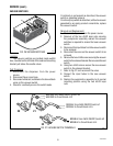
Removal and Replacement:
1. Disconnect the dispenser from the power source.
2. Remove the wires from the switch terminals.
3. Compress the clips inside on the back of the switch
panel and gently push the switch through the open-
ing.
4. Push the new switch into the opening and spread
the clips to hold the switch in the switch panel.
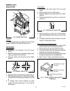
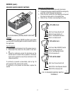
5. Refer to FIG. 21 when reconnecting the wires.
BLKfromMain
ON/OFF Switch
BLKtoCircuit
Board J4-3
RED/BLKfromPumpSwitch#1
RED/BLKtoRellSwitch#1
BRN/BLKfromPumpSwitch#2
BRN/BLKtoRellSwitch#2
WHI/RED from Pump Switch #3
WHI/RED to Refill Switch #3
BLU from Solenoid Switch #1
VIO from Solenoid Switch #2
WHI/VIO from Solenoid Switch #3
FIG. 21 TEST/OPERATE SWITCH TERMINALS
P1525
41093 040408