


Page 26
Removal and Replacement:
1. Remove the top cover or top warmer housing and
front access panel as previously described.
2. Disconnect the vent hose from the top of the tank
by pulling the elbow fitting from the grommet in
the top of the tank lid.
3. Drain water from the tank.
4. Disconnect the water supply tube to the dispense
valve from the side of the tank.
5. Disconnect the water supply tube to the solenoid
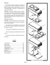
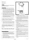
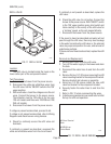
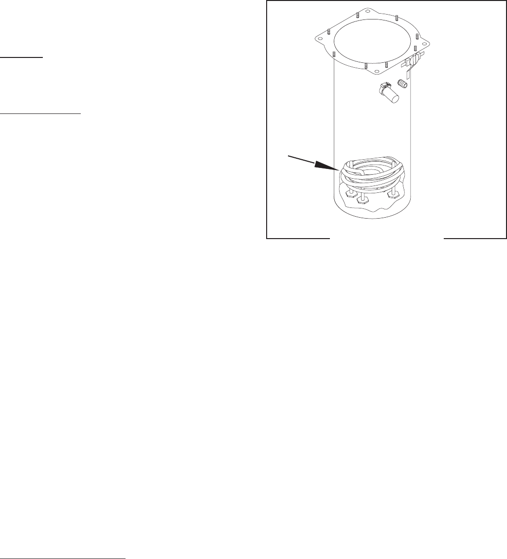
FIG. 8 TANK HEATERS
Location:
The tank heaters are located inside the tank and
secured to the tank bottom.
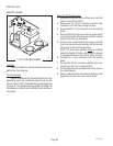
Test Procedures :
1. Disconnect the brewer from the power source.
2. With a voltmeter, check voltage across the white
or red wire from the terminal block and black wire
from the control board. Connect brewer to the
power source. The indication must be 120 volts ac
for two wire 120 volt models or 208-240 volts ac
for three wire 120/208-240 volt models.
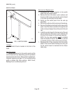
3. Disconnect the brewer from the power source.
4. Check voltage across the red wire from the termi-
nal block and black wire from the control board.
Connect brewer to the power source. The indica-
tion must be 208 or 240 volts ac.
5. Disconnect the brewer from the power source.
If voltage is present as described, proceed to #6
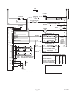
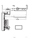
If voltage is not present as described, refer to the
Wiring Diagrams and check wiring harness.
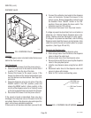
6. Disconnect the black and blue wires or the red and
white/violet wires from the tank heater terminals.
7. Check for continuity across tank heater terminals.
If continuity is present as described, reconnect the
wires, the tank heater is operating properly.
If continuity is not present as described, replace the
tank heater.
NOTE- If the tank heater remains unable to heat,
remove and inspect heater for cracks in the sheath.
P1890
SERVICE (cont.)
29707.1 082803
TANK HEATERS
valve from the bottom of the tank.
6. On brewers with faucet, disconnect the outlet
water line to the faucet from the side of the tank.
7. Disconnect the temperature probe from the top of
the tank by pulling the probe from the grommet in
the top of the tank lid.
8. Disconnect the pink wire from the level probe.
9. Disconnect the green wire from the top of the tank.
10. Disconnect the limit thermostat from the side of
the tank.
11. Disconnect the two white wires from the tank
warmer blanket.
12. Disconnect the black, blue, white/violet and red
wires from tank heater terminals.
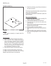
13. Remove the four #8-32 nuts securing the tank to
the mounting brackets and remove the tank as-
sembly.
14. Remove the eight #8-32 nuts securing the tank lid
to the tank.
15. Remove the two hex nuts securing the tank heater
to the bottom of the tank. Remove tank heater with
gaskets and discard.
16. Install new tank heater(s) with gaskets to the
bottom of the tank and secure with two hex nuts.
17. Install tank assembly onto mounting brackets and
secure in place with four #8-32 nuts.
18. Install tank lid and secure in place with eight #8-32
nuts.
19. Connect the two white wires of the tank warmer
blanket.