


Page 19
SERVICE (cont.)
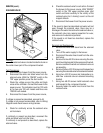
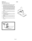
START SWITCH
B
U
N
N
M
A
N
U
F
A
C
T
U
R
E
D
B
Y
B
U
N
N
-
O
-
M
A
T
I
C
C
O
R
P
O
R
A
T
I
O
N
S
P
R
I
N
G
F
I
E
L
D
,
I
L
L
I
N
O
I
S
,
U
.
S
.
A
.
M
O
D
E
L
S
/
N
V
O
L
T
S
A
.
C
.
A
M
P
W
A
T
T
S
P
H
A
S
E
W
I
R
E
H
E
R
T
Z
C
O
V
E
R
E
D
U
N
D
E
R
O
N
E
O
R
M
O
R
E
O
F
T
H
E
F
O
L
L
O
W
I
N
G
P
A
T
E
N
T
S
:
O
N
E
O
R
M
O
R
E
O
T
H
E
R
P
A
T
E
N
T
S
M
A
Y
B
E
P
E
N
D
I
N
G
! CAUTION
FU
NN
E
L CO
N
TE
NTS
A
RE
HOT
D
IS
C
A
RD
D
E
C
A
NT
E
R
IF
:
•
C
R
A
C
K
E
D
•
S
C
R
A
T
C
H
E
D
•
B
O
I
L
E
D
D
R
Y
•
H
E
A
T
E
D
W
H
E
N
E
M
P
T
Y
•
U
S
E
D
O
N
H
I
G
H
F
L
A
M
E
O
R
E
X
P
O
S
E
D
E
L
E
C
T
R
I
C
E
L
E
M
E
N
T
S
P
N
:
0
0
6
5
8
.
0
0
0
0
D
3
/
9
7
©
1
9
8
5
B
U
N
N
-
O
-
M
A
T
I
C
C
O
R
P
O
R
A
T
I
O
N
R
E
A
D
T
H
E
E
N
T
I
R
E
O
P
E
R
A
T
I
N
G
M
A
N
U
A
L
B
E
F
O
R
E
U
S
I
N
G
T
H
I
S
P
R
O
D
U
C
T
F
A
I
L
U
R
E
T
O
C
O
M
P
L
Y
R
I
S
K
S
I
N
J
U
R
Y
P-150
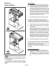
Location:
The start switch is located in the front of the
hood just to the right of center.
Test Procedure:
1. Disconnect the brewer from the power supply.
2. Disconnect the blue wire from the top switch
terminal and the white/red from the bottom switch
terminal.
3. Check for continuity across the two terminals on
the switch when it is held in the lower position.
Continuity must not be present across these
terminals in the upper position.
If continuity is present as described, reconnect the
blue wire to the top terminal and the white/red to the
bottom terminal.
If continuity is not present as described, replace the
switch.
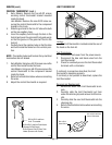
Removal and Replacement:
1. Remove the blue wire and white/red from the
start switch.
2. Compress the clips inside the hood and gently
push the switch through the opening.
3. Push new switch into the opening and spread the
clips to hold the start switch in the hood.
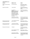
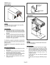
4. Refer to the following illustration when recon-
necting the wires.
BLU to BLU Lead
from Timer P1
WHI/RED to ON/OF
F
Switch
P1133
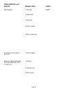
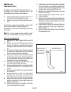
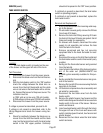
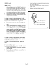
TANK HEATER
1
2
3
4
5
.5
MINUTES
BUNN-O-MATIC
P/N 2235-120 VAC
USE COPPER WIRE ONLY FOR
POWER SUPPLY CONNECTIONS
BUNN
C
W
S
E
R
I
E
S
R
E
A
D
Y
P1127
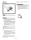
Location:
The tank heater is located inside the tank and
secured to the tank lid.
Test Procedures:
1. Disconnect the brewer from the power supply.
2. Check the voltage across the black and white
wires on 120 volt models or the black and red
wires for 120/240 volt models, with a voltmeter.
Connect the brew to the power source. The
indication must be:
a) 120 volts ac for two wire 120 volt 15 and 20
amp models .
b) 240 volts ac for three wire 120/240 volt mod-
els.