


Page 19
O
N
O
F
F
S
T
A
R
T
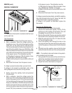
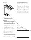
TANK HEATER
Location:
The tank heater is located inside the tank and
secured to the tank lid.
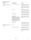
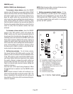
Test Procedures:
1. Disconnect the brewer from the power supply.
2. With a voltmeter, check the voltage across the
black and white wires on 120 volt models or the
black and red wires for 120/208 or 120/240 volt
models, 200 volt models and 240 volt models.
Connect the brew to the power source. The indica-
tion must be:
a) 120 volts ac for two wire 120 volt models .
b) 208 volts ac for three wire 120/208 and 240
volts ac for three wire 120/240 volt models.
c) 200 to 240 volts ac for two wire 200 or 240 volt
models.
3. Disconnect the brewer from the power source.
If voltage is present as described, proceed to #4.
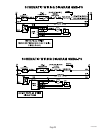
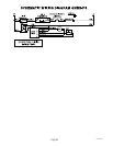
If voltage is not present as described, refer to the
Wiring Diagrams
and check wiring harness.
4. Disconnect the black wire and the white wire or red
wire from the tank heater terminals.
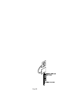
5. Check for continuity across the tank heater termi-
nals.
If continuity is present as described, reconnect the
wires, the tank heater is operating properly.
If continuity is not present as described, replace the
tank heater.
NOTE- If the tank heater remains unable to heat,
remove and inspect heater for cracks in the sheath.
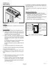
SERVICE (cont.)
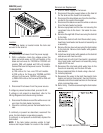
P2267
P1176
27479 121500
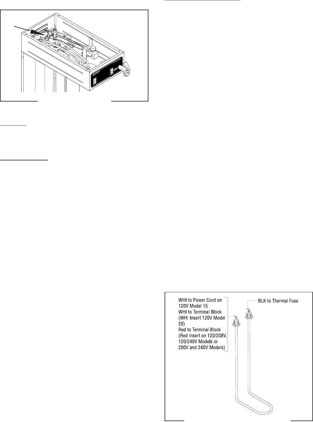
FIG. 13 TANK HEATER TERMINALS
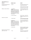
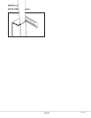
Removal and Replacement
1. Shut off water supply to the brewer.
2. Disconnect the water supply tubes on the tank lid
for the tank and the faucet coil assembly.
3. Disconnect the blue/black wire from the limit ther-
mostat to the control thermostat.
4. Disconnect the black wire and the white or red wire
from the tank heater terminals.
5. Remove sprayhead and the hex nut securing the
sprayhead tube to the hood. Set aside for reas-
sembly.
6. Remove the eight #8-32 nuts securing the tank lid
to the tank.
7. Remove the tank lid with limit thermostat, spray-
head tube, tank heater and faucet coil assembly as
a assembly.
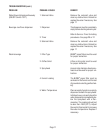
8 Remove the two hex nuts securing the tank heater
to the tank lid. Remove tank heater with gaskets
and discard.
10. Install new tank heater with gaskets on the tank lid
and secure with two hex nuts.
11. Install tank lid with limit thermostat, sprayhead
tube, tank heater and faucet coil assembly using
eight #8-32 hex nut.
12. Reconnect the inlet and outlet water lines to the
faucet coil assembly and the tank fill tube.
13. Secure spayhead tube to hood using a hex nut.
14. Install sprayhead.
15. Reconnect the wires to the limit thermostat, tank
heater and control thermostat. See limit thermo-
stat and control thermostat sections in this manual
when reconnecting wires.
16. Refer to Fig. 13 when reconnecting the tank heater
wires.
FIG. 12 TANK HEATER