


14
SERVICE (cont.)
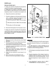
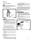
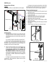
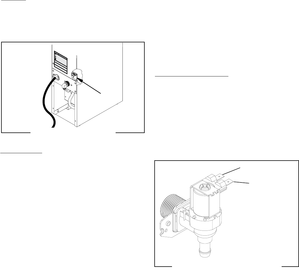
Solenoid Valve (Late Models)
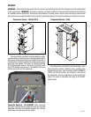
Location:
The solenoid valve is located inside the rear of the
dispenser on the right side near the bottom.
To test the solenoid valve, access will also be needed
to the electronic control board.
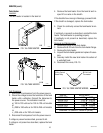
sound after approximately 5 seconds, as the coil
magnet attracts the plunger.
8. Disconnect the dispenser from the power source.
9. Reconnect the pink wire to terminal 5 of the elec-
tronic control board.
If the sound was heard as described and water will
not pass through the solenoid valve, there may be a
blockage in the water line before or after the solenoid
valve or the solenoid valve may require inspection for
wear and removal of waterborne particles.
If the sound was not heard as described, replace the
solenoid valve.
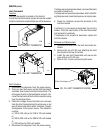
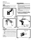
Removal and Replacement:
1. Remove all wires from the solenoid valve coil.
2. Turn-off the water supply to the dispenser.
3. Disconnect the water line from the solenoid valve.
4. Remove the two 8-32 slotted-head screws holding
the solenoid valve and mounting bracket to the back
panel.
5. Lift-out the solenoid valve.
6. Securely install the new solenoid valve to the back
panel.
7. Securely fasten the water line to the solenoid valve.
8. Reconnect the wires, FIG. 8.
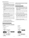
Fill wa ter tan k befor e turni ng -on
therm ostat o r conne cting a pplia nce
to powe r sourc e.
Do not us e near co mbust ibles .
Follo w
natio nal/l ocal el ectri cal cod es.
Elect rical ly grou nd the ch assis .
Use onl y on a prop erly pr otect ed
circu it capa ble of th e rated l oad.
FAILURE TO COMPLY RISKS EQUIPMENT
DAMA
GE, FIRE, OR SHOCK HAZARD
READ THE ENTIRE OPERATING MANUAL
INCLUDING THE LIMIT OF WARRANTY AND
LIABILITY BE
FORE BUYING OR USING THIS PRODUCT
THIS A
PPLIANCE IS HEATED WHENEVER
CON
NECTED TO A POWER SOURCE
00831.0000A 5/88 © 1988 BUNN-O-MATIC CORPORATION
WARNING
!
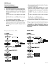
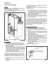
Test Procedure:
1. Disconnect the dispenser from the power source
and turn-off the water supply to the dispenser.
2. Remove the pink wire from terminal 5 of the elec-
tronic control board.
3. Check the voltage across the solenoid valve coil
terminals with a voltmeter. Connect the dispenser
to the power source. The indication must be:
a.) 100 to 120 volts ac for 100 to 120 volt models
or
b.) 200 to 240 volts ac for 200 to 240 volt models
or
c.) 230 volts ac for 230 volt models
after a delay of approximately 5 seconds.
4. Disconnect the dispenser from the power source.
If voltage was present as described, proceed to #5.
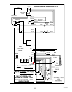
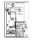
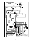
If voltage was not present as described, refer to the Wir-
ing Diagrams and check the dispenser wiring harness.
5. Remove both wires from the solenoid valve coil
terminals.
6. Check for continuity across the solenoid valve coil
terminals.
If continuity is present as described, reconnect the wires
and proceed to #7.
If continuity is not present as described, replace the
solenoid valve coil.
7. Check the solenoid valve for coil action. Connect
the dispenser to the power source. Listen carefully
in the vicinity of the solenoid valve for a “clicking”
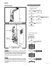
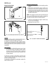
FIG. 14a SOLENOID VALVE
FIG. 14b SOLENOID VALVE WIRING
WHI/BLU to Electronic
Control Board T1
P1778
WHI or RED to
Terminal Block
42311 071310
H 5