


11
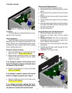
Location:
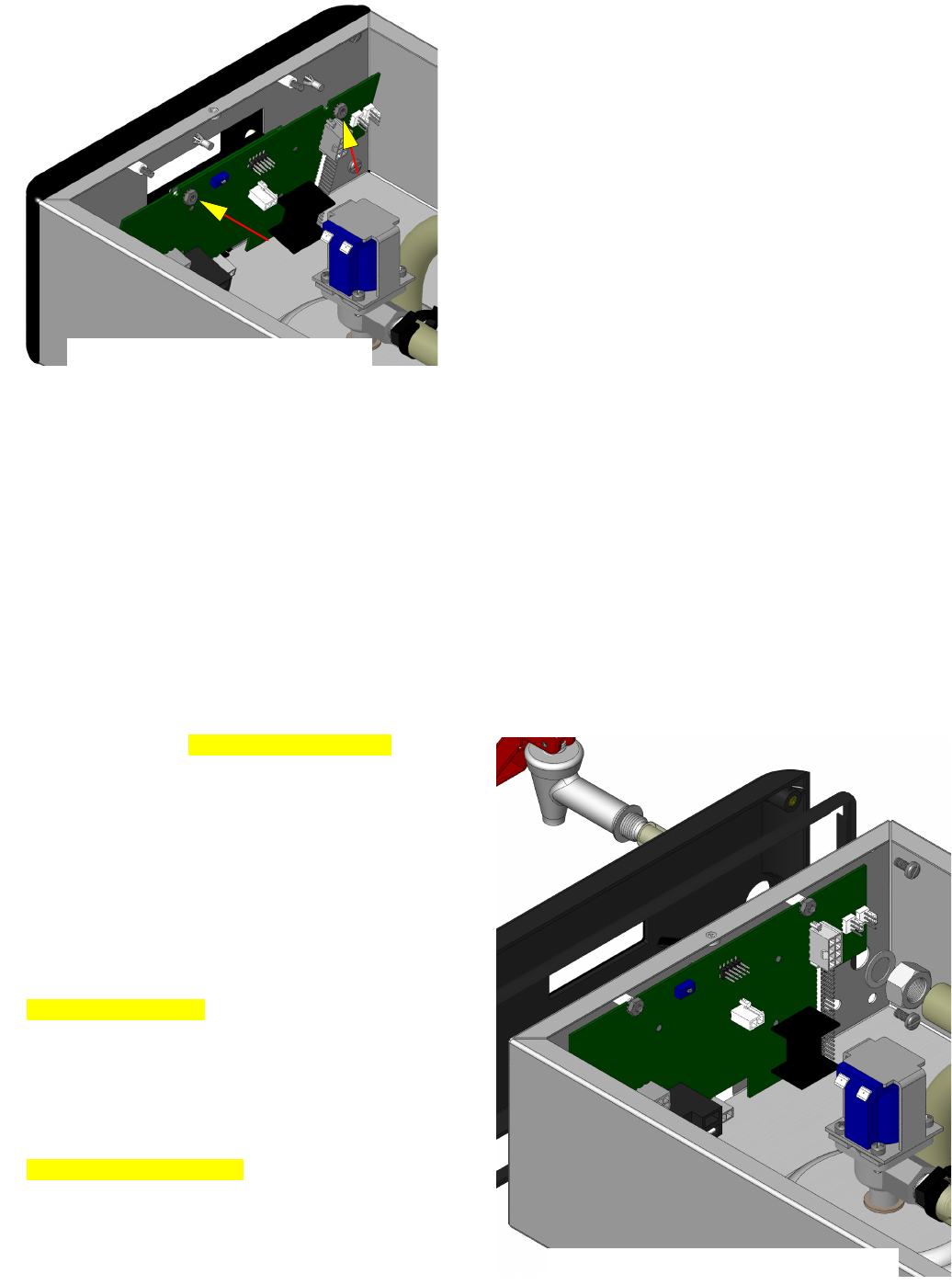
The Control Board is located inside the top cover
behind the front face plate.
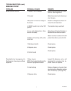
Test Procedures:
The test procedures for the control board will vary
depending upon the problems experienced by the
brewer. Refer to the Troubleshooting section which
is divided into three sections, Refi ll Circuit, Heating
Circuit, and Brewing Circuit.
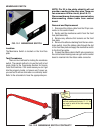
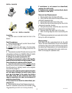
Check for Power to board:
Insert one meter lead in J17-pin 9 and the other 1.
lead in J17-pin 11 (TR-2 to TR-5 ITB only).
With the power connected to brewer, the voltage 2.
reading to the board should be the line voltage
rated for that model.
If no voltage is present, check wiring to the
board. If voltage is present, and brewer does
not power on, go to step 3
Check for line voltage at J15-1 BLK to J15-2 WHI 3.
(J14-1 to 2 ITB only)
If no voltage is present, replace the control
board. If voltage is present, go to step 4
Check for 12VAC at J15-4 to J15-2 Yellow wires 4.
(J14-4 to J14-5 ITB only)
If no voltage is present, replace the trans-
former. If voltage is present, and brewer does
not power on, replace the control board.
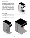
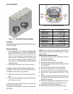
FIG. 11-1 CONTROL BOARD
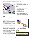
Removal and Replacement:
Disconnect brewer from power source.1.
Disconnect the wires from the relay on the control 2.
board.
Disconnect all of the connectors from the control 3.
board.
Remove the two nuts securing the control board 4.
to the hood.
Tilt the control board inward to clear the display 5.
section.
Place the bottom edge of the new control board in 6.
the cradle, tilt the board forward, and secure with
the two nuts to the hood.
Re-install connectors.7.
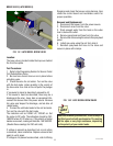
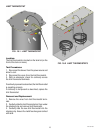
Faceplate Removal and Replacement:
Disconnect brewer from power source.1.
Disconnect the ribbon cable from the control 2.
board.
Models with faucet:3. Drain tank to below faucet
outlet fi tting. Remove hose, nut and washer from
faucet. Remove faucet assembly.
Remove the four screws securing the face plate 4.
to the hood.
Carefully pull the ribbon cable through the front 5.
opening of the hood.
Installation is the reverse order.6.
CONTROL BOARD
42461 0911809
FIG. 11-2 FACEPLATE REMOVAL