50
SERVICE (Cont.)
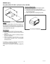
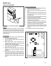
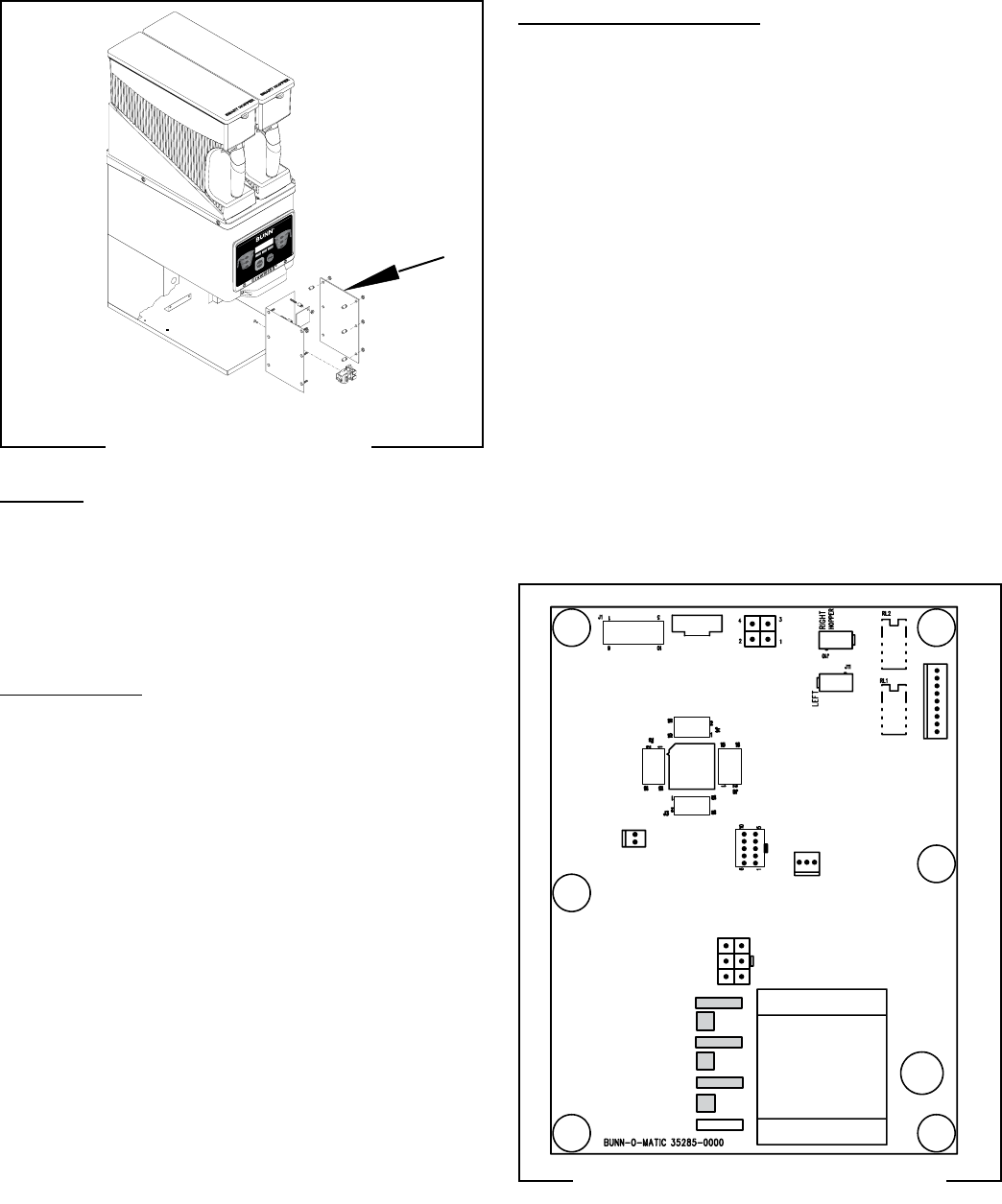
Control Board (Model MHG)
Location:
The control board is located on the component
mounting bracket mounted to the grinder base inside
the front access panel. The bracket can be removed by
loosening the two 8-32 screws securing the bracket to
the grinder base.
Test Procedure:
1. Press and hold the upper right hidden button to
enter the Programming menus.
2. Scroll to SERVICE TOOLS menu, and press the
button under "YES".
3. Press "YES" under TEST OUTPUTS and
proceed,through the menus to test the left and
right gates, and the grinder motor.
4. Then scroll to the TEST FREQUENCY menu and
press the button under "YES".
5. Observe the left, right and center frequency
screens, they should read between 124.0 and
126.0 khz.
6. Should any of the outputs or frequency tests fail,
first check the continuity of the wiring between the
component and the control board. Then test the
individual component before replacing the control
board.
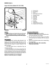
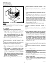
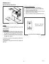
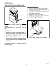
FIG 53 CONTROL BOARD
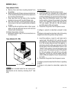
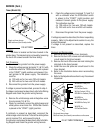
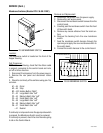
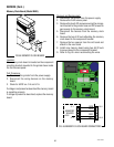
FIG 54 CONTROL BOARD TERMINALS
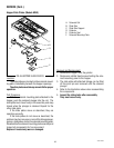
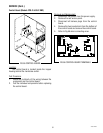
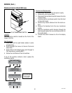
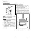
Removal and Replacement
1. Disconnect the grinder from the power supply.
2. Remove the front access panel.
3. Remove all wires from the control board termi-
nals.
4. Remove the bracket and control board by remov-
ing the two 8-32 screws securing the bracket to
the grinder base.
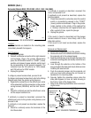
5. Remove the six 8-32 screws attaching the control
board the the component bracket.
6. Remove the six spacers from the old control board
and discard the control board.
7. Install the six spacers to the new control board
8. Attach the control board to the component bracket
using the six screws previously removed.
9. Position the bracket and control board assembly
in the grinder base and secure with the two 8-32
screws.
10. Reconnect the wires to the control board.
J12
J16
J8
J5
J9
MOV4
TH3
MOV3
TH2
MOV1
MOV2
TH1
J7
J13
41545 122209


