


Page 21
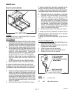
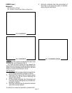
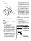
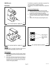
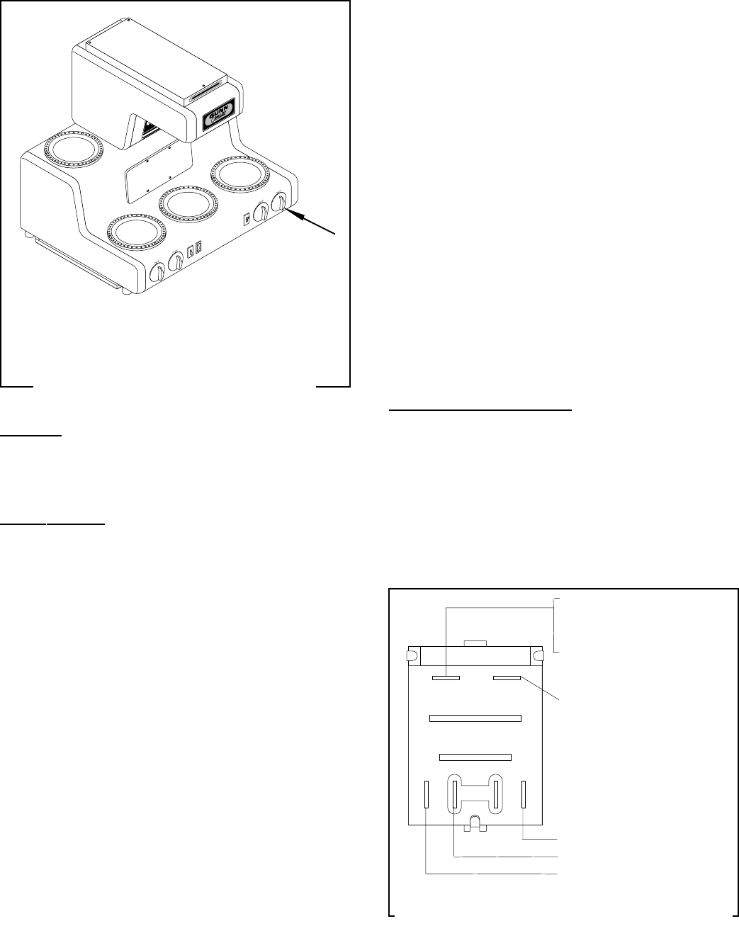
FIG. 18 THREE HEAT WARMER SWITCH
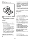
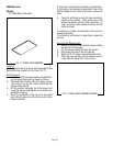
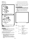
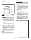
FIG. 19 THREE HEAT WARMER SWITCH WIRING
SERVICE (cont.)
Warmer Switch(es)
RT: Right Rear Three Heat Rotary
5. Check the voltage across terminals L1 and 2 with
a voltmeter when the switch is in the "High" posi-
tion. Connect the brewer to the power source.
The indication must be as described in step 1.
Voltage must not be present across these termi-
nals in the "Off", "Low", or "Med" positions.
6. Disconnect the brewer from the power source.
7. Check the voltage across terminals N and 1 with
a voltmeter when the switch is in the "Med" or
"High" positions. Connect the brewer to the power
source. The indication must be as described in
step 1. Voltage must not be present across these
terminals in the "Off" or "Low" positions.
8. Disconnect the brewer from the power source.
9. Check the voltage across terminals N and 2 with
a voltmeter when the switch is in the "Low" posi-
tion. Connect the brewer to the power source.
The indication must be as described in step 1.
Voltage must not be present across these termi-
nals in the "Off", "Med", or "High" positions.
10. Disconnect the brewer from the power source.
If voltage is present as described, the switch is oper-
ating properly.
If voltage is not present as described, replace the
switch.
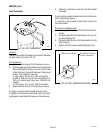
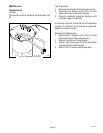
Removal and Replacement:
1. Remove the knob from the switch.
2. Loosen the 5/8" nut on the switch shaft and push
the switch through the opening.
3. Remove the wires from the switch terminals.
4. Refer to FIG. 19 when reconnecting the wires.
5. Securely mount the new switch onto the hous-
ing and reinstall the knob.
NOTE: Switch must be installed right side up.
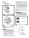
Location:
This switch is the farthest on the right of the base as
viewed from the front, FIG. 18. Its knob is marked
Off/Low/Med/High.
Test Procedure:
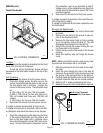
1. Check the voltage across terminals L1 and N with
a voltmeter. Connect the brewer to the power
source. The indication must be:
a) 120 volts ac for two wire 120 volt models.
b) 200 or 240 volts ac for two wire 200 volt or
240 volt models and three wire 120/240 volt
models.
c) 100 volts ac for two wire 100 volt models.
2. Disconnect the brewer from the power source.
If voltage is present as described, proceed to #3.
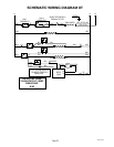
If voltage is not present as described, refer to the Wir-
ing Diagrams and check the brewer wiring harness.
3. Check the voltage across terminals L1 and 3 with
a voltmeter when the switch is in the "Low", "Med",
or "High" positions. Connect the brewer to the
power source. The indication must be as de-
scribed in step 1. Voltage must not be present
across these terminals in the "Off" position.
4. Disconnect the brewer from the power source.
W
A
R
N
IN
G
!
HIG
H H
EAT
W
AR
M
ER
DO
N
O
T
BOI
L D
EC
AN
T
ER
D
RY
K
EE
P C
O
M
BUS
TI
BL
E
S AW
A
Y
FA
ILU
R
E TO
C
OM
PL
Y
RI
SKS
GL
A
SS
FA
ILU
RE/HO
T L
I
QUID
BU
RN
S A
N
D
FIR
E H
A
ZA
R
D
CA
U
TIO
N
D
I
S
C
A
R
D
D
E
C
A
N
T
E
R
I
F
:
.
C
R
A
C
K
E
D
.
S
C
R
A
T
C
H
E
D
.
B
O
I
L
E
D
D
R
Y
.
H
E
A
T
E
D
W
H
E
N
E
M
P
T
Y
.
U
S
E
D
O
N
H
I
G
H
F
L
A
M
E
.
O
R
E
X
P
O
S
E
D
E
L
E
C
T
R
I
C
E
L
E
M
E
N
T
S
F
A
I
L
U
R
E
T
O
C
O
M
P
L
Y
R
I
S
K
S
I
N
J
U
R
Y
P
N
:
6
5
8
1
9
8
5
B
U
N
N
-
O
-
M
A
T
IC
C
O
R
P
O
R
A
T
I
O
N
F
U
N
N
E
L
C
O
N
T
E
N
T
S
A
R
E
H
O
T
!
NL1
12 3
WHI or RED to Terminal Block
WHI or RED to Right Front
Warmer
WHI or RED to Indicator Lamp
RED or BLACK to Terminal
Block
RED to Right Rear Warmer
BRN to Right Rear Warmer
WHI to Right Rear Warmer
P1688
P1696
10021 071700