


Page 21
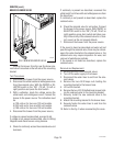
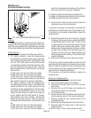
DILUTION SOLENOID VALVE(S)
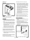
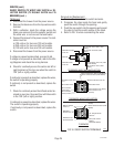
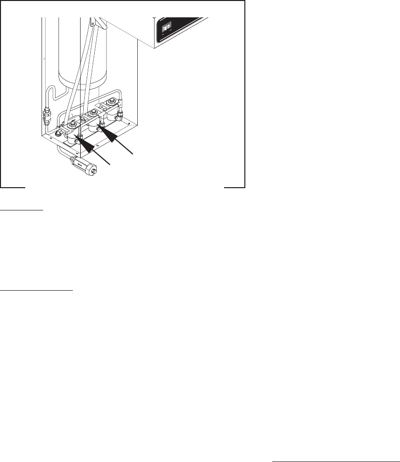
FIG. 10 DILUTION SOLENOID VALVE(S)
P2207.40
Location:
Viewing the brewer from the rear the dilution so-
lenoid for the T3 is mounted on the center of the sole-
noid mounting bracket, the T6 solenoids are mounted
in the center and the right side of the mounting bracket.
Test Procedure:
1. Disconnect the brewer from the power source.
2. T3 - With a voltmeter, check the voltage across
the white/blue and white/violet wires on the dilu-
tion solenoid terminals when the ON/OFF switch
is in the “ON” (left) position and the start switch
is momentarily placed in the lower position. Con-
nect the brewer to the power source. After the
approximate setting on the delay dial, the indica-
tion must be:
a) 120 volts ac for two wire 120 volt models.
b) 240 volts ac for two wire 240 volt models.
c) 100 volts ac for two wire 100 volt models, re-
main for the approximate setting on the dilution
dial, and then return to its previous indication.
T6 - With a voltmeter, check the voltage across
the white/blue and yellow wires on the dilution so-
lenoid terminals for the right reservoir and the
white/blue and the brown/black for the left reser-
voir when the SELECTOR switch is in the “ON”
(left for the left reservoir or right for the right res-
ervoir) position and the start switch is momen-
tarily placed in the lower position. Connect the
brewer to the power source. After the approxi-
mate setting on the delay dial, the indication must
be:
a) 120 volts ac for two wire 120 volt models.
b) 240 volts ac for two wire 240 volt models.
c) 100 volts ac for two wire 100 volt models, re-
SERVICE (cont.)
main for the approximate setting on the dilution
dial, then return to its previous indication.
If voltage is present as described, proceed to #4.
If voltage is not present as described, refer to the
Wir-
ing Diagrams
and check the wiring harness.
4. Remove both wires from the coil and check for
continuity across the coil terminals.
If continuity is present as described, reconnect the
white/blue and white/violet wires and proceed to #5.
If continuity is not present as described, replace the
solenoid valve.
5. Check the solenoid valve for coil action. Connect
the brewer to the power source, place the ON/OFF
or SELECTOR switch in the “ON” (T3 left, T6 left
or right) position and momentarily place the start
switch in the lower position and release. Listen
carefully after the approximate setting on the de-
lay dial in the vicinity of the solenoid valve for a
“clicking” sound as the coil magnet attracts and
after the approximate setting on the dilution dial,
repels the plunger.
6. Disconnect the brewer from the power source.
If the sound is heard as described and water will not
pass through the solenoid valve, there may be a block-
age in the water line before or after the solenoid valve
or, the solenoid valve may require inspection for wear,
and removal of waterborne particles.
If the sound is not heard as described, replace the
solenoid valve.
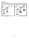
Removal and Replacement:
1. Remove all wires from the solenoid valves.
2. Turn off the water supply to the brewer.
3. Disconnect the water lines to and from the sole-
noid valves.
4. Remove the two #8-32 keps nuts holding the
mounting bracket to the trunk base.
5. Lift out the bracket.
6. Remove the two #10-32 slotted-head screws hold-
ing the solenoid valve to the mounting bracket.
7. Securely install the new solenoid valve to the
mounting bracket.
8. Attach the mounting bracket to the trunk base.
9. Securely fasten the water lines to and from the
solenoid valves.
10. Refer to Fig. 3 when reconnecting the wires.
10145 072600