


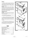
Page 18
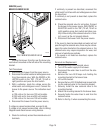
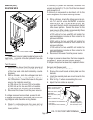
Location:
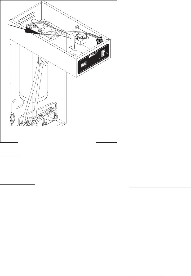
The timer is located inside the hood, attached to
the left side.
Test Procedure.
NOTE: Do not remove or install wires while timer board
is installed. Pressure applied to one side may cause
damage to the board.
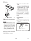
1. Disconnect the brewer from the power source and
remove the front access panel.
2. Remove the two #8-32 screws securing circuit
board to the mounting bracket.
3. Remove circuit board and spacers (as required).
4. With a voltmeter, check the voltage across termi-
nals TL1 and TL2 when the "ON/OFF" switch is in
the "ON" position. Connect the brewer to the power
source. The indication must be:
a) 120 volts ac for two wire 120 volt models.
b) 240 volts ac for two wire 240 volt models.
c) 100 volts ac for two wire 100 volt models.
5. Disconnect the brewer from the power source.
If voltage is present as described, proceed to #6.
If voltage is not present as described, refer to the
Wiring Diagrams
and check the brewer wiring har-
ness.
6. With a voltmeter, check the voltage across termi-
nals TL1 and TL4 when the "ON/OFF" switch is in
the "ON" position. Connect the brewer to the power
source. The indication must be 0 volts.
If voltage is as described, proceed to #7.
If voltage is not as described, disconnect the brewer
from the power source and replace the timer.
7. With a voltmeter, check the voltage across termi-
nals TL1 and TL4 when the "ON/OFF" switch is in
the "ON" position. Connect the brewer to the power
source and press the "START" switch. The indica-
tion must be as follows:
a) 120 volts ac for two wire 120 volt models.
b) 240 volts ac on two wire 240 volt models.
c) 100 volts ac for two wire 100 volt models.
If voltage is present as described, the brew timer is
operating properly. Reset the timer as required, to
obtain the desired brew volume.
If voltage is not present as described, disconnect the
brewer from the power source and replace the timer.
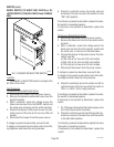
Removal and Replacement:
1. Remove the two #8-32 screws securing circuit
board to the mounting bracket.
2. Remove circuit board and spacers (as required).
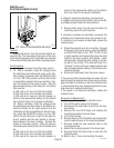
3. Remove all wires from the timer.
4. Attach all wires to the replacement timer board
prior to installation to the component mounting
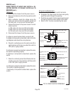
bracket. Refer to FIG. 7 when reconnecting the
wires.
5. Install new circuit board with spacers (as re-
quired) to the component mounting bracket.
6. Adjust the timer as described below.
Timer Setting:
NOTE: Prior to setting or modifying volumes, check
that the brewer is connected to water supply, the tank
is properly filled, and a funnel and server are in place.
NOTE: All volume settings must be done with the
sprayhead installed.
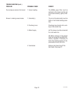
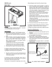
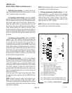
SERVICE (cont.)
DIGITAL BREW TIMER (Late Models)
10145 072600
FIG. 6 DIGITAL BREW TIMER
P2207.50