


Page 4
ELECTRICAL REQUIREMENTS
CAUTION - The brewer must be disconnected from the power source until specifi ed in Initial Set-Up.
120V model brewers require 2-wire, grounded service rated 120 volts ac, 15 amp, single phase, 60 Hz.
"A" model brewers require 2-wire, grounded service rated 230 volts ac, 10 amp, single phase, 50 Hz.
"B" model brewers require 2-wire, grounded service rated 100 volts ac, 15 amp, single phase, 60 Hz.
WARNING - If the power cord is ever damaged, it must be replaced by the manufacturer or its service agent with
a special cord available from the manufacturer or its service agent in order to avoid a hazard.
Proceed as follows:
Electrical Hook-Up
CAUTION – Improper electrical installation will damage electronic components.
1. An electrician must provide electrical service as specifi ed.
2. Using a voltmeter, check the voltage and color coding of each conductor at the electrical source.
3. Remove top cover from the brewer.
4. Rotate the control thermostat knob fully counterclockwise to the "OFF" position and replace the top cover.
5. Connect the brewer to the power source.
6. If plumbing is to be hooked up later be sure the brewer is disconnected from the power source. If plumbing
has been hooked up, the brewer is ready for Initial Set-Up.
PLUMBING REQUIREMENTS
These brewers must be connected to a cold water system with operating pressure between 20 (138) and 90
psi (620 kPa) from a
1
⁄2" or larger supply line. A shut-off valve should be installed in the line before the brewer.
Install a regulator in the line when pressure is greater than 90 psi (620 kPa) to reduce it to 50 psi (345 kPa). The
water inlet fi tting is
1
⁄4" fl are.
NOTE - Bunn-O-Matic recommends
1
⁄4" copper tubing for installations of less than 25 feet and
3
⁄8" for more than 25
feet from the
1
⁄2" water supply line. A tight coil of copper tubing in the water line will facilitate moving the brewer
to clean the countertop. Bunn-O-Matic does not recommend the use of a saddle valve to install the brewer. The
size and shape of the hole made in the supply line by this type of device may restrict water fl ow.
This equipment must be installed to comply with the Basic Plumbing Code of the Building Offi cials
and Code Administrators International, Inc. (BOCA) and the Food Service Sanitation Manual of the
Food and Drug Administration (FDA). For models installed outside the U.S.A., you must comply with
the applicable Plumbing/Sanitation Code for your area.
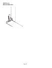
1. Remove the shipping cap from the bulkhead fi tting on the rear of the brewer.
2. Flush the water line and securely attach it to the bulkhead fi tting on the rear of the brewer.
3. Turn on the water supply.
NOTE: TheFlow Control/Strainer assembly is internal, located inside the back panel.
37235 050506