


Page 19
SERVICE (cont.)
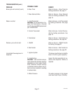
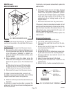
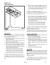
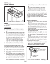
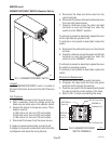
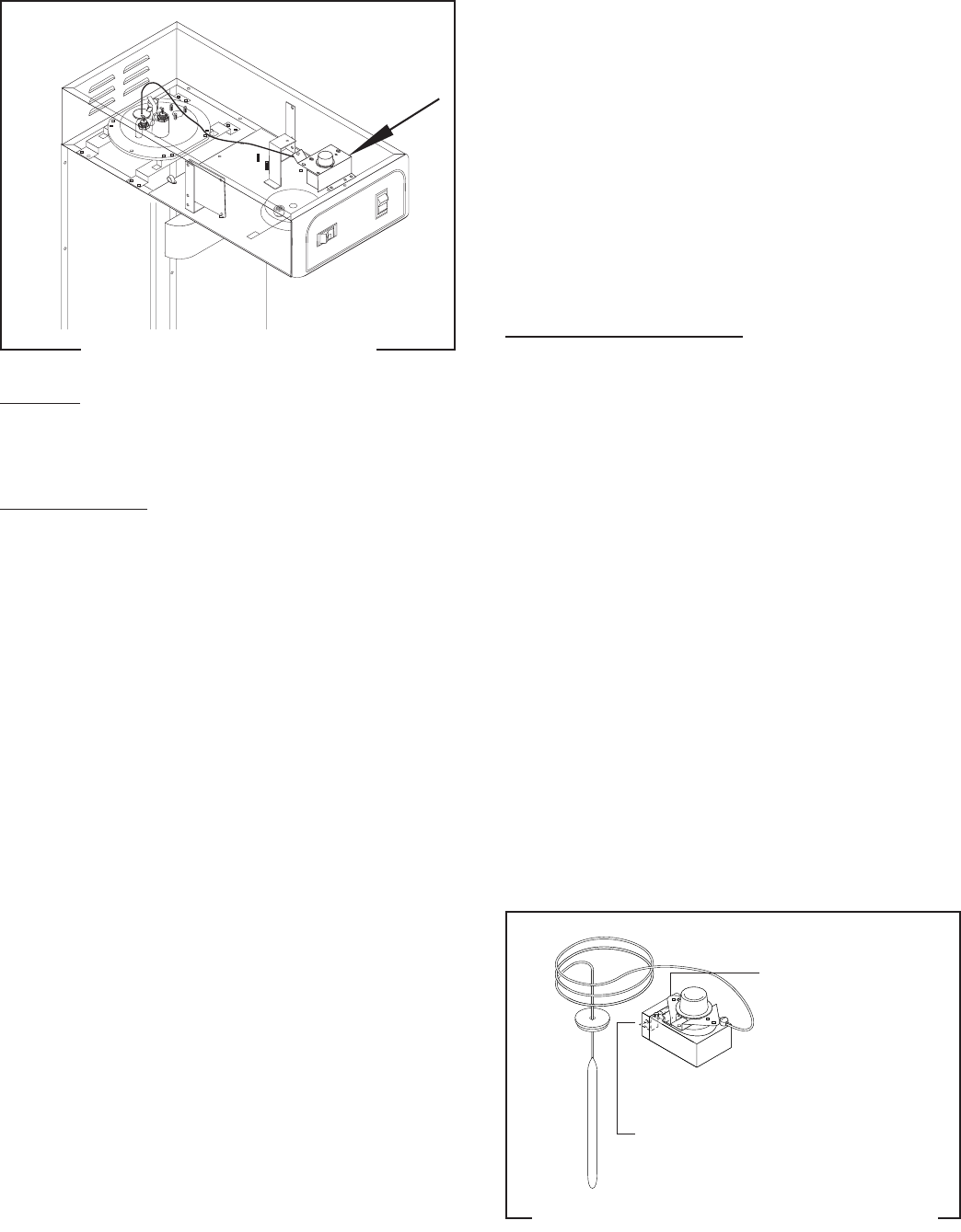
CONTROL THERMOSTAT
FIG. 6 CONTROL THERMOSTAT
P3047
Location:
The control thermostat is located inside hood on
the right side.
Test Procedures:
1. Disconnect the brewer from the power source.
2. Locate the blue/black wire on the control thermo-
stat.
3. With a voltmeter, check the voltage across the blue/
black wire on the control thermostat and the white
wire on the tank heater for 100 volt and 120 volt
two wire models or red wire on the tank heater for
230 volt two wire models. Connect the brewer to
the power source. The indication must be:
a) 120 volts ac for two wire 120 volt models.
b) 230 volts ac for two wire 230 volt models.
c) 100 volts ac for two wire 100 volt models.
4. Disconnect the brewer from the power source.
If voltage is present as described, proceed to #5.
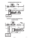
If voltage is not present as described, refer to the wir-
ing diagrams and check the brewer wiring harness.
5. Locate the black wire on the control thermostat.
6. Gently remove the capillary bulb and grommet
from the tank.
7. With a voltmeter, check the voltage across the
black wire of the control thermostat and the white
wire on the tank heater for 100 volt and 120 volt
two wire models or red wire on the tank heater for
230 volt two wire models when the control ther-
mostat is turned fully clockwise. Connect the
brewer to the power source. The indication must
be:
a) 120 volts ac for two wire 120 volt models.
b) 230 volts ac for two wire 230 volt models.
c) 100 volts ac for two wire 100 volt models.
8. Disconnect the brewer from the power source.
If voltage is present as described, reinstall the capil-
lary tube into the tank to the line 5.5" above the bulb,
the control thermostat is operating properly.
If voltage is not present as described, replace the ther-
mostat.
Removal and Replacement:
1. Remove both wires from the control thermostat
terminals.
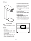
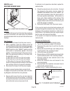
2. Remove the thermostat capillary bulb by firmly
pulling up on the capillary tube at the tank lid. This
will disengage the grommet from the tank lid.
3. Remove the #8-32 screw holding the control ther-
mostat to its bracket.
4. Slide the grommet to the line 5.5" above the bulb
on the new capillary tube.
5. Insert the capillary bulb through the hole in the
tank lid and press the grommet firmly and evenly
so that the groove in the grommet fits into the
tank lid.
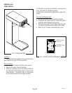
6. Carefully bend the capillary tube so that the tube
and bulb inside the tank are in a vertical position.
NOTE: The capillary tube must be clear of any elec-
trical termination and not kinked.
7. Fasten the new control thermostat to its bracket.
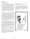
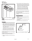
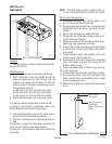
8. Refer to Fig. 7 when reconnecting the wires.
9. Adjust the control thermostat as required.
FIG. 7 CONTROL THERMOSTAT TERMINALS
BUNN
OFF
HI
BUNN
OFF
HI
BLK to
Tank Heater (100/120V)
Thermal Fuse (230V)
BLU/BLK to Limit
Thermostat
P2090.80
37236 080504