


16
Gas supply connection
• Check that the appliance is set for the type of gas available
and then connect it to the mains gas piping or the gas
cylinder in compliance with current regulations and
standards.
• This appliance is designed and set to work with the gas
indicated on the label situated on the actual hob. If the gas
supply is other than the type for which the appliance has
been set, proceed with replacing the corresponding nozzles
(provided), following instructions given in the paragraph
“Adaptation to different types of gas”.
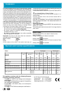
• For trouble-free operation, suitable use of energy and
longer life of the appliance, make sure that the supply
pressure complies with the values indicated in the table 1
"burners and nozzles specifications, otherwise install a
special pressure regulator on the supply pipe in compliance
with current standards and regulations.
• Connect in such a way that the appliance is subjected to
no strain whatsoever.
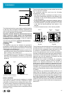
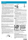
Either a rigid metal pipe with fittings in compliance with the
standards in force must be used for connecting to the nipple
union (threaded ½"BSP male fitting) situated at the rear of the
appliance to the right (fig.3), or flexible steel pipe in compliance
with the standards in force, which must not exceed 2000 mm
in length.
Should it be necessary to turn the fitting, the gasket (supplied
with the appliance) must be replaced.
Upon completion of installation, check the gas circuit, the
internal connections and the taps for leaks using a leak-
detection fluid. Also check that the connecting pipe cannot
come into contact with moving parts which could damage or
crush it. Make sure that the natural gas pipe is adequate for
a sufficient supply to the appliance when all the burners are
lit.
Important: A pressure regulator, in compliance with the
standards in force, must be inserted when connecting to a
liquid gas supply (in a cylinder).
Adaptation to a different type of gas
If the hob is to be converted for use with a type of gas other
than that for which it was set in the factory (indicated on the
label to be found on the hob), the burner nozzles should be
replaced as follows:
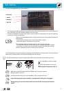
• Remove the pan supports and the burners.
• Unscrew the nozzles “A” (fig.4) using a 7 mm socket
wrench and replace them with the ones which have a
diameter suitable for the type of gas to be used, according
to the table 1 "burners and nozzles specifications).
• On completing the operation, replace the old rating label
with the one showing the new type of gas; the sticker is
available from our Service Centres.
• Reassemble the parts following the instructions in reverse
order.
A
fig.4
fig.3
Minimum Regulation
• Turn the gas valve to minimum.
• Remove the tap knob and turn the adjusting screw, situated
inside of the tap stem (fig.5), using a screwdriver (loosening
the screw increases the height of the flame, tightening
decreases it).
N.B.: In the case of liquid gas, the regulation screw must
be fully screwed in (clockwise).
• Make sure that, when the knob is turned rapidly high to
low, the flame does not go out.
• In the event of a malfunction on appliances with the
security device (thermocouple) when the gas supply is
set at minimum, increase the minimum supply levels using
the regulator screw.
Once the adjustment has been made, apply sealing wax,
or a suitable substitute, to the old seals on the by-pass.
Replacing the nozzles on separate “double flame “
burners:
• remove the grids and slide the burners from their
housings. The burner consists of 2 separate parts (Fig.
C and fig. D);
• unscrew the burers with a 7 mm wrench spanner. The
internal burner has a nozzle, the external burner has
two (of the same size). Replace the nozzle with models
suited to the new type of gas (see table 1).
• replace all the components by repeating the steps in
reverse order.
Fig. C Fig. D
Regulation of Air Supply to the Burner
The burners do not need a primary air regulator.
Electrical connection
THE APPLIANCE MUST BE EARTHED
The hob is designed to work with alternating current at the
supply voltage and frequency indicated on the rating plate
(situated under the hob or at the end of the instruction
booklet). Make sure that the local supply voltage corresponds
to the voltage indicated on the rating plate.
Connecting the supply cable to the mains electricity
supply
fig.5
Installation