3
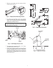
1. Slide the screen display onto the mounting bracket.
(location shown in Fig. 3).
2. Two hooks secure the display screen to the mounting
bracket. Hold the display screen until verifying that the
display screen is supported by the hooks on the mounting
bracket before releasing. See Fig. 4.
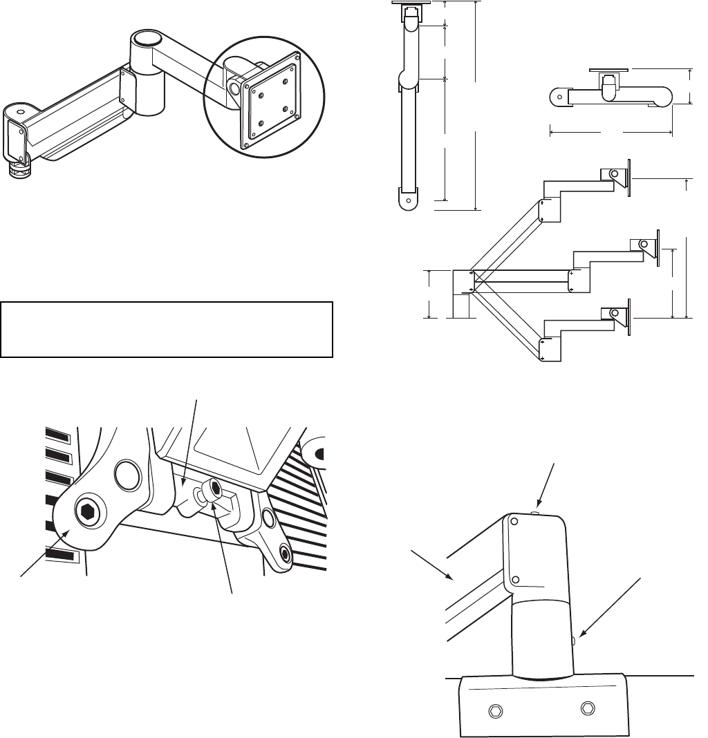
3. The display height is adjustable within a 15.9 in. range.
Arm dimensions are shown in Fig. 5.
4. Using a hex screwdriver, secure the arm from pulling out
of the mount by tightening the hex screw on the side of
the mount. The display screen can now be positioned to
desired height. To adjust tension on the up and down
movement of the arm, tighten the hex screw on the top of
the arm mount (Fig. 6).
IMPORTANT: To prevent damage to display screen,
do not mount the display on the arm until arm is com-
pletely attached to the tube sheet.
Fig. 3 — Display Screen Mounting Location
MOUNTING
BRACKET
a19-1892
Fig. 4 — Bolt Display Screen to Arm
MOUNTING
BRACKET
RETAINING
BOLT
DISPLAY
MOUNT
a19-1893
MAX
HORIZONTAL
RANGE
24.1"
MAX
VERTICAL
RANGE
15.9"
3.1"
3.5"
6.7"
13.3"
15.3"
7.1"
5.6"
Fig. 5 — Display Arm Dimensions
a19-1894
Fig. 6 — Adjust Arm Tension
HEX SCREW TO
ADJUST ARM
TENSION
ARM
HEX SCREW
TO SECURE
ARM TO ARM
BASE
a19-
1891


