


2
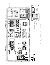
Table 1 — Terminal Block (TB) Locations Containing LEN Connector
Table 2 — 30RB315-390 Modular Unit Combinations
UNIT MODEL
LOCATION DESCRIPTION OF TB CONTAINING LEN CONNECTOR
30HK,HL040-060
TB3 can be accessed without opening the control box door. It is located at the upper right corner
of the control box.
30HW018-040
TB3 can be accessed without opening the control box door. It is located at the upper right corner
of the control box.
30RB060-120
TB3 can be accessed by opening the control box door. It is located at the right side of the hinged
display door.
30RB130-300
TB3 can be accessed by opening the left hand (smaller) door of the fan control panel. It is
located at the right side of the display panel.
30RB315-390
Unit sizes 30RB315-390 are modular units and thus, accept two Navigator™ modules, one on
each unit module. See Table 2.
48PG03-16 (TB1) 48PG20-28 (TB2)
50PG03-16 (TB1) 50PG20-28 (TB2)
Both TBs are accessed by opening the control box door. TB1 (PG03-16) or TB2 (PG20-28) is
located in the lower right of the control box.
48AJ,AK,AW,AY020-060
50AJ,AK,AW,AY020-060
TB3 can be accessed by opening the control box door. It is located in the lower center of the
control box.
NOTE: If the unit is equipped with an Economizer Circuit Board (ECB), the ECB provides an
auxiliary RJ14 LEN connector. See product documentation for more detail.
48ZG,ZN,ZT,ZW,Z6,Z8
50ZG,ZN,ZT,ZW,ZX,ZZ,Z2,Z3,Z6,Z7,Z8,Z9
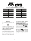
TB3 can be accessed by opening the control box door. It is located to the left of the Scrolling
Marquee (display).
NOTE: These units provide an auxiliary RJ14 LEN connection on the corner post on the enter-
ing air end of the unit. See product documentation for more detail.
UNIT SIZE Module A Module B
30RBA315 30RBA160 30RBA160
30RBA330 30RBA170 30RBA160
30RBA345 30RBA170 30RBA170
30RBA360 30RBA190 30RBA170
30RBA390 30RBA190 30RBA190
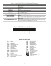
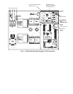
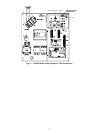
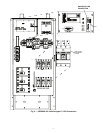
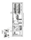
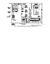
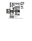
LEGEND FOR FIG. 2 - FIG. 8
A—Alarm
AUX — Auxiliary
C—Contactor, Compressor
CAP — Capacitor
CB — Circuit Breaker
CB-FN — Circuit Breaker Fan Circuit
CB-HT — Circuit Breaker Cooler Heater
CB-P — Circuit Breaker Pump
CCB — Control Circuit Board
CCN — Carrier Comfort Network
CLHR — Cooler Heater Relay
CR — Control Relay
CS — Current Sensor
CSB — Current Sensor Board
DS — Disconnect Switch
ECB — Economizer Circuit Board
EMM — Energy Management Module
EQUIP — Equipment
EXV — Electronic Expansion Valve
EXVB — EXV Board
FB — Fuse Block
FB1 — Fan Board 1
FC — Fan Contactor
GCS — Ground Current Sensing
GND — Ground
HACR — Heating, Air Conditioning, and Refrigeration
IDR — Inducer Draft Relay
IFC — Indoor Fan Contactor
IFCB — Indoor Fan Circuit Breaker
MMC — Motormaster® Contactor
MMR — Motormaster Relay
OFC — Outdoor Fan Contactor
PLP — Phase Loss Protection
RCB — Rooftop Control Board
LEN — Local Equipment Network
MBB — Main Base Board
NEC — National Electrical Code
PMP — Pump Contactor
POT — Potentiometer
RRB — Reverse Rotation Board
SW — Switch
TB — Terminal Block
TDR — Time-Delay Relay
TRAN — Transformer
TXV — Thermostatic Expansion Value
Terminal Block Connection
Field Power Wiring
Factory Wiring
Field Wiring
Accessory or Option Wiring
To indicate common potential only, not to
represent wiring