


3
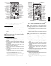
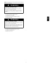
COMBUSTION-AIR
INTAKE
CONNECTION
GAS VALVE
VENT OUTLET
CONDENSATE
TRAP
MOTOR AND
BLOWER
ASSEMBLY
AIR FILTER AND
RETAINER
PRESSURE
SWITCHES
INDUCER MOTOR
AUXILIARY
JUNCTION BOX
CONDENSING
HEAT
EXCHANGER
(BEHIND CELL
INLET PANEL)
BURNER
ENCLOSURE
VENT OUTLET
CONTROL
CENTER
BLOWER
ACCESS PANEL
SAFETY
INTERLOCK
SWITCH
CAP AND
CLAMP
(UNUSED
DRAIN
CONNECTION)
PRIMARY HEAT
EXCHANGER
(BEHIND CELL
INLET PANEL)
A01026
Fig. 1 -- Two--Stage, Two--Speed and Fixed--Capacity
Model(s) in Upflow Orientation
Remove Inducer
Assembly
1. If not previously disconnected, disconnect inducer motor
wire connector at quick--connect.
2. If not previously disconnected, disconnect pressure switch
wires.
3. Remove collector box pressure switch tube from pressure
switch.
4. Remove four screws attaching inducer housing to cell pan-
el.
NOTE: Inducer housing, inducer motor, and pressure switch(es)
should be removed as 1 assembly.
Install Primary Cell Inlet
Panel
1. Remove four screws attaching condensing heat exchanger
assembly to primary cell inlet panel.
2. Remove screws attaching primary cells to primary cell in-
let panel.
3. Remove main limit and shield from primary cell inlet pan-
el. Note orientation of shield and direction of main limit
for reassembly.
4. Remove primary cell inlet panel by lifting panel off con-
densing heat exchanger collector box.
5. Slide new inlet cell panel over condensing heat exchanger
collector box.
6. Attach primary cell inlet panel to primary cells by doing
the following:
a. Center primary cell inlet panel over primary cell open-
ings.
b. Use an awl to align holes and start ALL screws
(provided in kit) in primary cells.
c. After all screws are started, check position of fiberglass
gasket and tighten screws in cells.
7. Install main limit and shield in primary cell inlet panel.
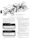
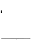
BURNER
ENCLOSURE
PRIMARY HEAT
EXCHANGER
(BEHIND CELL
INLET PANEL)
GAS VALVE
CAP AND
CLAMP
(UNUSED
DRAIN
CONN.)
INDUCER
MOTOR
VENT
OUTLET
PRESSURE
SWITCHES
BLOWER
ACCESS
PANEL
SAFETY
INTERLOCK
SWITCH
MOTOR AND
BLOWER ASSEMBLY
AIR FILTER
AND RETAINER
CONDENSATE
TRAP
INDUCER
HOUSING
DRAIN TUBE
CONDENSING
HEAT
EXCHANGER
(BEHIND CELL
INLET PANEL)
INDUCER MOTOR
WIRE
CONNECTOR
VENT OUTLET
AUXILIARY
JUNCTION BOX
COMBUSTION-
AIR INTAKE
CONNECTION
CONTROL
CENTER
A93407
Fig. 2 -- Variable--Speed Model in Upflow Orientation
NOTE: Visually check location of main limit and shield to
ensure shield is not touching primary cells. If shield is touching,
short cycling of limit will occur.
8. Reinstall condensing heat exchanger assembly to primary
cell inlet panel.
Reinstall Inducer
Assembly
1. Inspect connector box gasket where inducer housing will
mate.
NOTE: If gasket is damaged in any way, it must be repaired. To
repair, apply a small bead of G.E. RTV 162, G.E. 6702, or
Dow--Corning RTV 738 to damaged gasket area. Apply sealant
releasing agent such as PAM cooking spray or equivalent (must
not contain corn nor canola oil, halogenated hydrocarbons or
aromatic content to prevent inadequate sealing) to inducer
housing mating surface.
2. Attach inducer assembly to cell panel by aligning four
screws through inducer housing spacers. Tighten screws to
secure.
3. Attach collector box pressure switch tube to pressure
switch. See tubing diagram of furnace for proper location
attachment.
4. If control was removed from furnace with whole cell panel
assembly, reconnect inducer motor wire connector at
quick--connect.
5. If control was removed from furnace with whole cell panel
assembly, reconnect pressure switch wires. Refer to wiring
diagram on furnace for proper attachment.
Reinstall Burner Enclosure
Assembly
1. Position burner enclosure gasket between the burner box
and inlet cell panel and secure burner box on inlet cell
panel using screws removed earlier.
2. Connect pressure tube to gas valve.
3. Inspect gasket, then install intake housing on burner en-
closure.
320720