


4
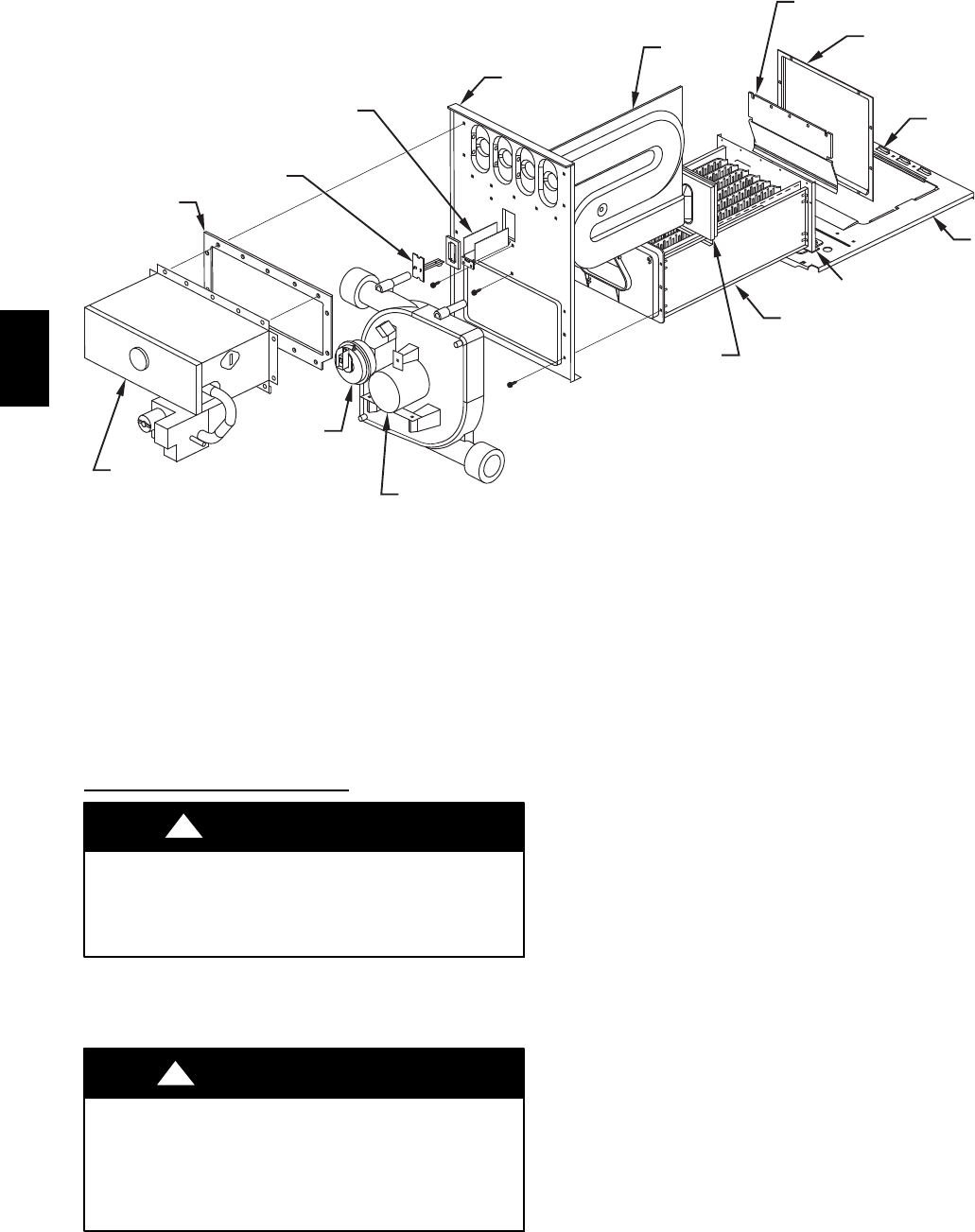
COUPLING
BOX
T-TABS
BLOWER
SHELF
PRESSURE
SWITCH
BURNER
ENCLOSURE
AND GAS VAVLE
INDUCER
MOTOR
BURNER
ENCLOSURE
GASKET
MAIN LIMIT
MAIN LIMIT
SHIELD
PRIMARY CELL
INLET PANEL
PRIMARY
CELL
CONDENSING
HEAT EXCHANGER
ASSEMBLY
PRIMARY CELL
OUTLET PANEL
COLD SPOT
BAFFLE
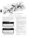
NOTE: ACTUAL COMPONENT LOCATION MAY VARY
DEPENDING ON MODEL & SERIES.
CONDENSING
HEAT EXCHANGER
CELL REAR PANEL
A05128
Fig. 3 -- Expanded View of Heat System Components in Upflow Orientation
NOTE: If gasket is damaged in any way, it must be repaired. To
repair, apply a small bead of G.E. RTV 162, G.E. 6702, or
Dow--Corning RTV 738 to damaged gasket area. Apply sealant
releasing agent such as PAM cooking spray or equivalent (must
not contain corn nor canola oil, halogenated hydrocarbons or
aromatic content to prevent inadequate sealing) to burner
enclosure mating surface.
4. Connect pressure tube to intake housing.
Reinstall Whole Cell Panel
Assembly
PERSONAL INJURY HAZARD
Failure to follow this caution may result in personal injury.
Whole cell panel assembly is heavy. Get help to lift and
install.
CAUTION
!
1. Install whole cell panel assembly with heat exchanger,
burner box, inducer assembly, J--box (if applicable), and
control center (if applicable) through front of furnace.
FIRE AND UNIT OPERATION HAZARD
Failure to follow this warning could result in personal
injury, death and / or property damage.
DO NOT cut or tear foil face insulation. If cuts or tears
occur, repair insulation with foil tape.
!
WARNING
2. Secure whole cell panel assembly to blower shelf by in-
stalling two screws through blower housing (four screws
on 120 and 140 sizes) and two screws next to blower
housing.
NOTE: When reinstalling condensing heat exchanger assembly,
the lower flange of the condensing heat exchanger cell rear panel
must engage on the T--tabs in rear blower shelf. (See Fig. 3.)
3. Install three screws to each side of inlet cell panel and into
cell panel supports.
4. If previously removed, reinstall control center in casing
flange.
5. If control center is located in burner compartment or fur-
nace, reinstall blower motor leads, transformer wires, door
switch wires, and auxiliary limit switch wires (if present)
through blower shelf and grommet.
6. If control is located in blower compartment of furnace,
pull wires to flame sensor, hot surface igniter, overtemper-
ature switch, gas valve, pressure switch(es), inducer motor,
limit switch, and J--box through blower shelf.
7. Install J--box.
8. Reattach wires to control center or components. See wir-
ing diagram on furnace for proper attachment.
9. Reinstall condensate trap where previously installed fur-
nace casing or blower shelf.
10. Reconnect condensate trap drain tubes. See tubing dia-
gram on furnace for proper tube location.
11. Connect field drain to condensate trap.
NOTE: Ensure tubes are not kinked or pinched, as this will
affect operation.
12. Connect vent pipe by inserting pipe into coupling, elasto-
meric (rubber) coupling, and then fully into inducer hous-
ing outlet.
13. Connect combustion--air intake pipe to intake housing and
install screw to secure. Do not use RTV unless previously
used.
14. Install top filler panel.
15. Install gas supply pipe to gas valve using backup wrench.
320720