


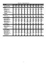
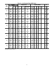
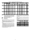
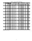
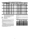
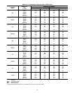
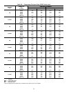
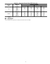
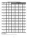
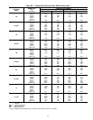
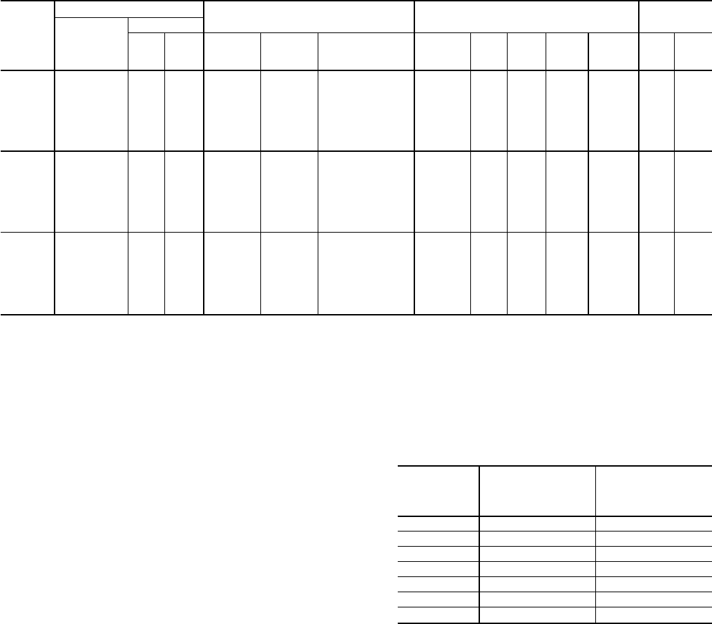
Table 4A — Unit Electrical Data, 30HXC Units* (cont)
UNIT
30HXC
VOLTAGE
POWER CIRCUIT CONTROL CIRCUIT ICF
Nameplate
(3 Ph)
Supplied
Min Max MCA MOCP
Recommended
Fuse Size
Voltage
(Single
Ph)
Min Max MCA MOCP WD XL
161
208/230-60 187 253 285/197 500/350 350/250 115-60 104 127
15 15
591 †
460-60 414 506 200 300 250 115-60 104 127 287 756
575-60 518 633 160 225 200 115-60 104 127 230 605
380-60 342 418 242 350 300 230-60 207 254 325 843
230-50 207 253 266/182 450/300 350/225 230-50 198 254 578 †
346-50 325 380 273 400 350 230-50 198 254 394 †
380/415-50 342 440 249 350 300 230-50 198 254 358 944
171
208/230-60 187 253 238/285 400/500 300/400 115-60 104 127
15 15
624 †
460-60 414 506 215 300 250 115-60 104 127 302 771
575-60 518 633 172 250 200 115-60 104 127 242 617
380-60 342 418 260 350 300 230-60 207 254 343 861
230-50 207 253 219/266 350/450 300/350 230-50 198 254 607 †
346-50 325 380 145/176 250/300 175/225 230-50 198 254 413 †
380/415-50 342 440 267 350 300 230-50 198 254 376 962
186
208/230-60 187 253 285/285 500/500 400/400 115-60 104 127
15 15
661 †
460-60 414 506 232 300 300 115-60 104 127 319 788
575-60 518 633 185 250 225 115-60 104 127 255 630
380-60 342 418 156/156 250/250 200/200 230-60 207 254 364 882
230-50 207 253 266/266 450/450 350/350 230-50 198 254 645 †
346-50 325 380 176/176 300/300 225/225 230-50 198 254 438 †
380/415-50 342 440 289 400 350 230-50 198 254 399 985
LEGEND
ICF — Maximum Instantaneous Current Flow during start-up
(the point in the starting sequence where the sum of the
LRA for the start-up compressor, plus the total RLA for
all running compressors, plus the total FLA for all run-
ning fan motors is at a maximum)
MCA — Minimum Circuit Ampacity (for wire sizing)
MOCP — Maximum Overcurrent Protection
RLA — Rated Load Amps
WD — Wye-Delta Start
XL — Across-the-Line Start
*Refer to Carrier’s electronic catalog for the most current electrical
data.
†Wye-Delta Start is standard. Not available in across-the-line start.
**The 30HX186 units have 2 terminal blocks/non-fused disconnects
and 6 parallel conductors/non-fused disconnects.
††The 30HXC171 and 186 units have 2 terminal blocks/non-fused
disconnects and 6 parallel conductors/non-fused disconnects.
NOTES:
1. Main power must be supplied from a field-supplied fused electri-
cal service with a (factory- or field-installed) disconnect located in
sight from the unit.
2. Control circuitpower mustbe supplied froma separatesource through
a field-supplied disconnect. The control circuit accessory trans-
former may be applied to power from the main unit power supply.
3. Maximum incoming wire size for each terminal block is 500 kcmil.
4. Maximum allowable phase imbalance is: voltage, 2%; amps, 5%.
5. Units with one MCA value have one main terminal block. Units
with 2 MCA values require multiple conductors.
6. Use copper conductors only.
7. The MOCP is calculated as follows:
MOCP = (2.25) (largest RLA) + the sum of the other RLAs. Size
the fuse one size down from the result. The RLAs are listed on the
unit nameplate.
The recommended fuse size in amps (RFA) is calculated as
follows:
RFA = (1.50) (largest RLA) + the sum of the other RLAs. Size
the fuse one size up from the result. The RLAs are listed on the
unit nameplate.
8. Units have the following power wiring terminal blocks and parallel
conductors:
VOLTAGE
TERMINAL
BLOCKS
OR NON-FUSED
DISCONNECTS
PARALLEL
CONDUCTORS
OR NON-FUSED
DISCONNECTS
208/230 26
460 13
575 13
380** 13
230 26
346†† 13
380/415 13
16