


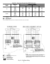
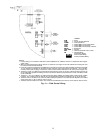
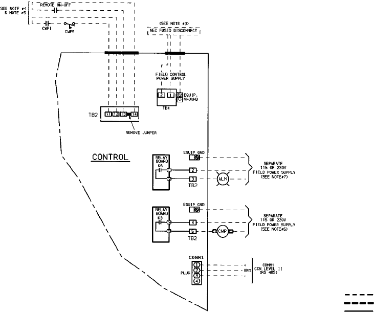
LEGEND
ALM — Alarm
CCN — Carrier Comfort Network
COMM — Communications
CWFS — Chilled Water (Fluid) Flow Switch
CWP — Chilled Water (Fluid) Pump
CWPI — Chilled Water (Fluid) Pump Interlock
EQUIP — Equipment
GND, GRD — Ground
NEC — National Electrical Code (U.S.A.)
TB — Terminal Block
Field Power Wiring
Field Control Wiring
Factory-Installed Wiring
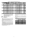
NOTES:
1. Factory wiring is in accordance with NEC. Field modifications or additions must be in compliance with all appli-
cable codes.
2. Wiring for main field supply must be rated 75° C minimum. Use copper for all units. Maximum incoming wire size
for each terminal block is 500 kcmil.
3. Power for control circuit should be supplied from a separate source through a field-supplied, fused disconnect with
15 amp maximum protection for all control circuits. Connect control circuit power to terminals 1 and 2 of TB4.
Connect neutral side of supply to terminal 2 of TB4. Control circuit conductors for all units must be copper only.
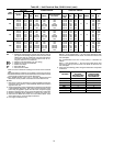
4. Terminals 13 and 14 of TB2 are for field external connection for remote on-off. The contacts must be rated for dry
circuit application capable of handling a 24 vac to 50 mAload. Remove jumper between 13 and 14 of TB2 if remote
on-off is installed.
5. Terminals 11 and 12 of TB2 are for chilled water flow switch (CWFS) and chilled water pump interlock (CWPI)
functions. The contacts must be rated for dry circuit application capable of handling a 24 vac to 50 mA load.
6. Terminals 4 and 5 of TB2 are for control of chilled water pump starter. The maximum load allowed for the chilled
water pump relay is 125 va sealed, 1250 va inrush.
7. Terminals 2 and 3 of TB2 are for alarm. The maximum load allowed for the alarm is 125 va sealed, 1250 va inrush.
Fig. 13 — Field Control Wiring
25