


4
AIR SUPPLY AND VENTILATION: Adequate ventilation and air supply
must be provided in order for the coffee urn to operate properly and
efficiently. The area in front of and above the unit must be clear to avoid
any obstruction of flow of combustion and ventilation air. DO NOT under
any circumstances, connect the coffee urn flue directly to a building
exhaust system or place the flue outlet directly into the plenum of the
exhaust hood as it will adversely affect the gas combustion of the coffee
urn.
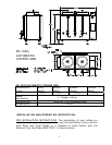
CLEARANCES: Your coffee urn is design certified to use on combustible
floors. The side and back clearances for combustible constructions are as
follows: 6 inches from side and 8 inches from back. The coffee urn must
be installed with 4 inch high legs provided.
GAS CONNECTION: Examine the gas specification label attached to the
urn to be certain that the type of gas for which the unit is equipped is
the same as the gas supply. A 3/8 NPT gas connection is needed to
connect the unit to the gas line. An accessible manual shut-off valve
must be installed in the gas supply line in case of an emergency. The gas
supply pipe must be sized to accommodate all the gas fired equipment
that may be connected to it. Check with your local Gas Company as to
proper pipe size. Sealant on all pipe joints must be resistive to propane
gas. Before attempting to light the coffee urn, check all joints for gas
tightness using a soap and water solution.
WATER CONNECTION: Unit is supplied with a water strainer and a 19”
length of ¼” copper tubing with a flare fitting. Connect the copper tubing
with the flare fitting to the water connection at the rear of the machine.
The other end of the strainer is connected with a suitable length of ¼”
tubing and a shut-off valve (supplied by a plumber) to a cold water
supply. Water pressure should be minimum of 20 lbs. for proper
operation.
To turn on the water supply valve plug the line cord into a 120 V
grounded outlet. The water will start entering the unit and automatically
fill it to capacity.
LIGHTING AND ADJUSTMENT:
Water must be visible in the sight glass
before lighting to pilot. Turn the thermostat knob to its lowest position.
Turn gas cock dial to PILOT position. Depress gas cock dial and light pilot
with a long lighted match through the opening located on the bottom of
the urn. Hold in depressed position for approximately 30 sec. or until
pilot remains lit when dial is released.
NOTE: On the first lighting it may be necessary to hold the dial for a
longer period to allow trapped air to escape from the line.
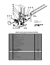
DIAL SETTINGS AND CORRESPONDING WATER TEMPERATURES:
“1”= 50F, “10”=198F