


5
S190006
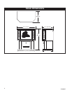
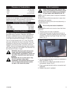
Clearance to Combustibles
Back . . . . . . . . . . . . . . . . . . . . . . . . . . . . .2” (51 mm)
Sides . . . . . . . . . . . . . . . . . . . . . . . . . . . .6” (153 mm)
Floor . . . . . . . . . . . . . . . . . . . . . . . . . . . . . .0” (0 mm)
Top . . . . . . . . . . . . . . . . . . . . . . . . . . . .24” (610 mm)
Hearth
A hearth is not mandatory, but is recommended for
aesthetic purposes. We recommend a noncombustible
hearth which does not obstruct heater openings.
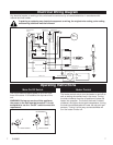
Electric Specifications
Voltage . . . . . . . . . . . . . . . . . . . . . . . .120V AC/60Hz
Total Amps . . . . . . . . . . . . . . . . . . . . . . .12.20 Amps
Total Watts . . . . . . . . . . . . . . . . . . . . . . . .1460 Watts
Heater Ratings . . . . . . . . . . . . . . . . . . . .1300 Watts
Electrical Connection
A 15 Amp, 120 Volt, 60 Hz circuit with a properly
grounded outlet is required. Preferably, the appliance
will be on a dedicated circuit as other appliances on
the same circuit may cause the circuit breaker to trip
or the fuse to blow when the heater is in operation.
The unit comes standard with a 6’ (1.8m) long three
wire cord, exiting from the rear of the stove. Plan the
installation to avoid the use of an extension cord. If an
extension cord must be used, it must be a minimum
14AWG, three wire with grounding type plug connector
and rated not less than 1875 Watts. The cord shall not
be more than 20’ (6m) in length.
WARNING: Electrical outlet wiring must
comply with local building codes and
other applicable regulations to reduce the
risk of fire, electrical shock and injury to
persons.
WARNING: Do not use this stove if any
part of it has been under water.
Immediately call a qualified service tech-
nician to inspect the stove and replace
any part of the electrical system.
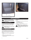
Fan Kit Installation
When installed, the heater must be elec-
trically connected and grounded in accor-
dance with local codes, or in th absence
of local codes, with ANSI/NFPA No. 70.
NOTE: 110/120 electric power is required to operate
blower (fan).
Be sure to leave sufficient excess wire in case minor
adjustments are required.
Any electrical re-wiring of this fan must be done by a
qualified electrician.
Turn off all power before installation.
CAUTION: Be careful not to touch or bend the flame
generator.
1. Remove panel from back of pedestal
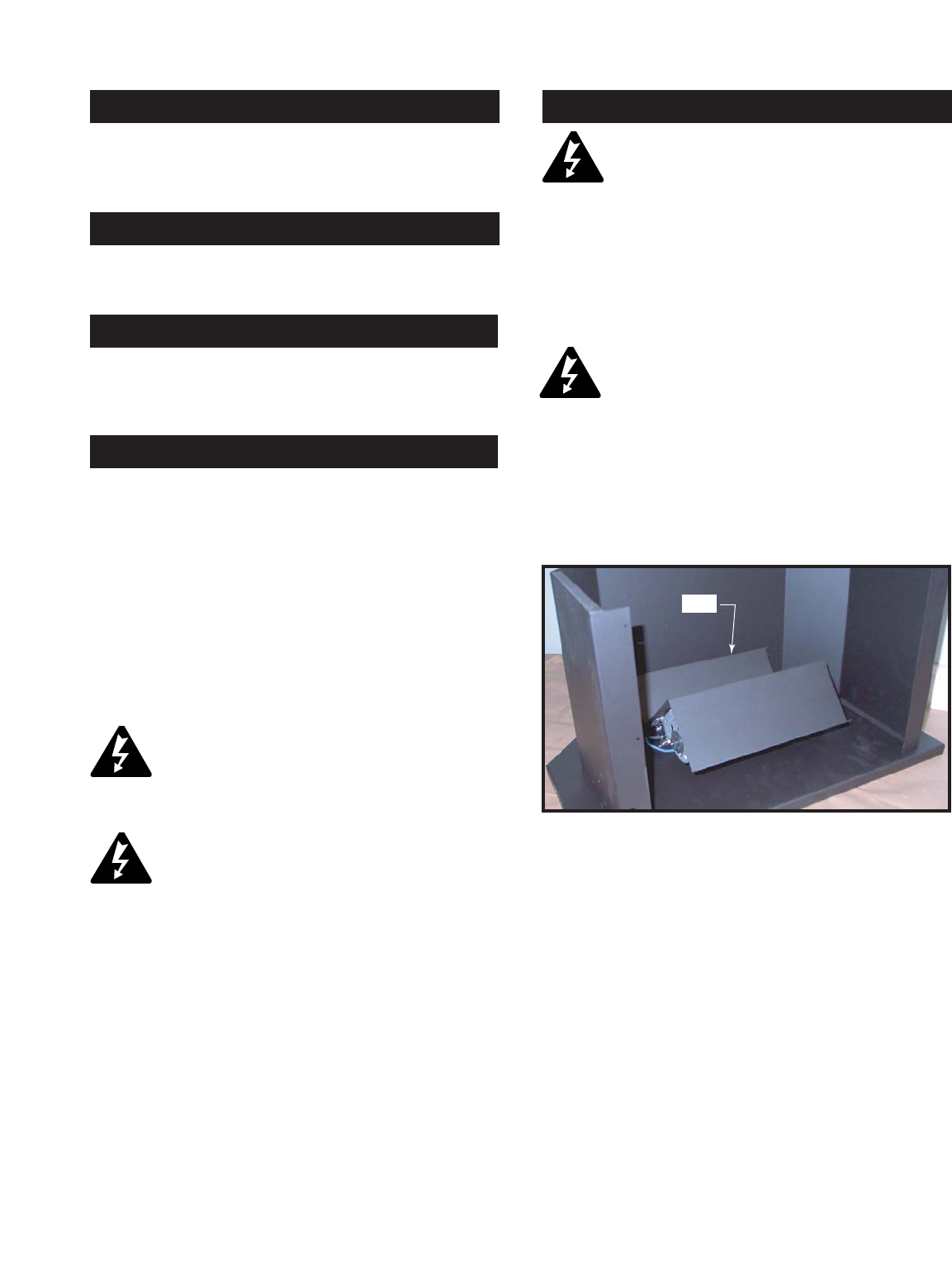
2. Install the fan through the opening at the back of
the pedestal. Place fan assembly as far forward as
possible, inserting long flange through slot in front
panel. (Fig. 1)
3. Use two screws provided to secure fan assembly to
base of pedestal. (Fig. 2)
4. From front of unit, attach brass handle to front of
fan assembly flange. (Fig. 3)
5. Plug in grounded service cord to a convenient wall
receptacle.
6. Replace rear panel in pedestal.
Slot
ST824
Fig. 1 Insert flange through slot in front panel.