


13
Pinnacle & Stardance Direct Vent - Rear Vent Gas Heaters
20007066
If you are not installing a fan, proceed to the
appropriate vent assembly section.
Install Optional Fan Kit #2960/FK28
Fan Kit Contents:
• #10 x 1/2" phillips screws, 6
• Control Knob
• Retainer Collar
• Snapstat • Snapstat Bracket
• Blower Assembly w/ Rheostat Control
NOTE: The Rheostat Assembly and the Snapstat
Assembly are not used on RF Models.
For RF Models only: Follow Step 3, then run the
spliced female leads to the front of the stove and attach
to PC board of RF valve. Then follow Step 5.
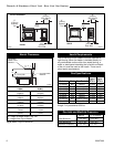
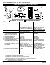
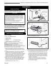
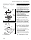
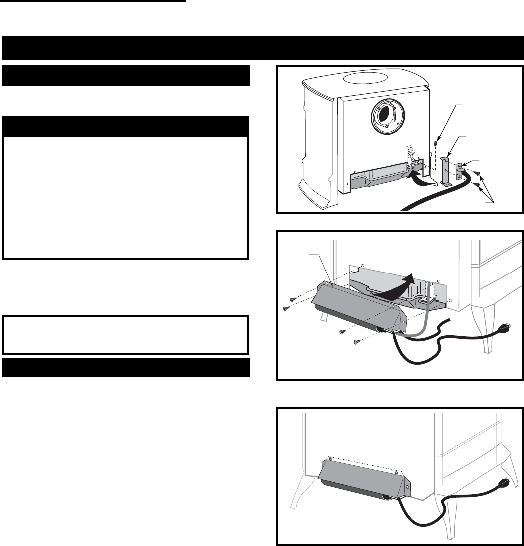
1. Attach the Snapstat to the Bracket using two #10 x
1/2" phillips sheet metal screws as shown in Figure
12.
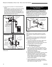
2. Locate and remove the 1/4-20 x 3/8" hex head bolt
installed in the hole in the right rear ledge of the
firebox. (Fig. 11) Use that bolt to secure the Snapstat
Bracket to the firebox. The mounting hole is slotted
to allow you to adjust the bracket so that its head
makes contact with the firebox surface. (Fig. 11)
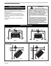
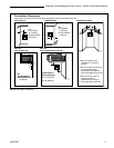
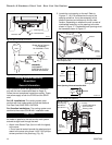
3. Attach the Fan to the firebox by engaging the upper
flange of the fan skirt under the lower edge of the
Shroud and secure the skirt with the four screws
provided with the kit. (Figs. 12, 13)
Upper
Flange
ST240
Fig. 12 The upper flange of the fan skirt should be located
behind the lower edge of the shroud.
Installation
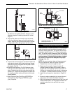
NOTE: Verify the two relief doors (located on top of
the firebox) are properly seated on the gasket. The
doors sit flush on the gasket, and should lift easily
from the seal around the opening.
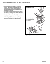
ST241
Fig. 13 Correct position of fan skirt installation.
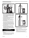
4. The rheostat control switch attaches to the left side of
the valve bracket at the front of the stove. (Fig. 14)
• Insert the switch box shaft through the hole in the
back of the right side of the valve bracket, aligning
the locator pin with the smaller hole in that bracket.
• Attach the retaining nut to the switch control shaft
to secure it to the plate.
• Attach the Control Knob to the rheostat shaft.
• Use the wire tie to secure the fan and rheostat
wire harnesses together.
1/4-20 x 3/8”
Hex Head Bolt
Bracket
Snapstat
1/2” Sheet
Metal Screws
FK101a
Fig. 11 Snapstat assembly and installation.
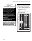
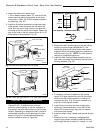
Unpack the Stove
The stove is shipped fully assembled on its back.
Unpack the stove and carefully set it upright.
CAUTION
Porcelain enamelled surfaces are fragile. Handle
porcelain enamelled castings tenderly. Familiarize
yourself with the assembly steps before you begin
and proceed with deliberation and care. If possible,
have assistance available.
Place enamelled castings on a soft, cushioned
surface until you are ready to assemble.
Avoid contact between the castings and other hard
surfaces or objects.