


24
Pinnacle & Stardance Direct Vent - Rear Vent Gas Heaters
20007066
Thermostat
Wire / Gauge Maximum Run
18 40 feet
20 25 feet
22 16 feet
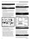
Thermostat Connection
(Optional) R Models Only
Use only a thermostat rated for 500 - 750 millivolts.
Check the table below for the appropriate gauge
thermostat wire to use for the length of lead required in
your installation.
1. Install the wall thermostat in the desired location
and run the wires to the stove location. Terminate
these leads with 1/4” female connectors.
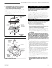
2. Connect the thermostat wires to the valve. (Fig. 41)
This completes assembly of the PDV20 and SDVR
stove.
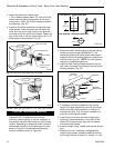
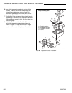
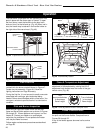
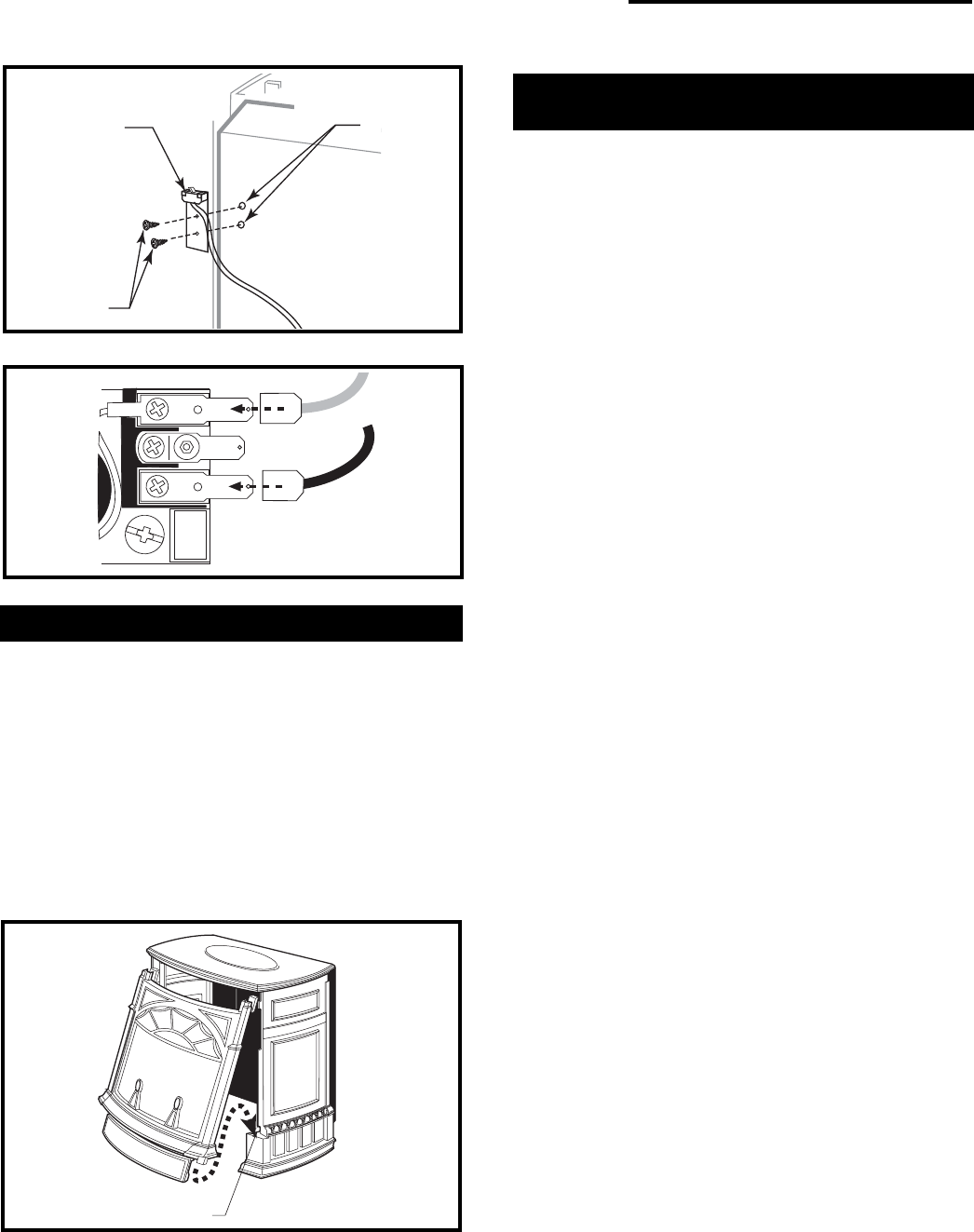
Install the Front Plate
Grasp the Front Plate and lift it into position, engaging
the two steel tabs at the upper corners behind the
adjacent bosses in the Side Plates. (Fig. 42) Seat the
Front against the Sides so that the tabs at the bottom
lip engage with the notches in the edge of the stove
base.
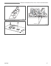
When properly installed, the bottom of the Front Plate
cannot be pulled away from the sides without also
lifting it up.
If you are installing optional Warming Shelves, do so now,
according to the instructions supplied with that kit.
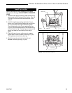
PILOT
ADJ
TP
TH
TPTH
ST228
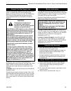
Fig. 41 Attach switch wires to valve.
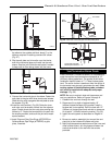
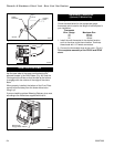
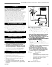
Switch
Assembly
Screws
Existing
Holes
ST315
Fig. 40 Attach switch assembly to rear shroud.
Fig. 42 Install Stove Front.
ST407
Bottom Tabs
Engage Notch in Base