


7
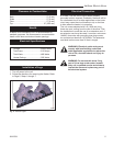
Addison Electric Stove
30002351
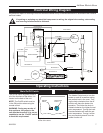
Any electrical repairs or rewiring of this unit should be carried out by a licensed electrician in accordance with national
and local codes.
If repairing or replacing any electricial component or wiring, the original wire routing, color coding
and securing locations must be followed.
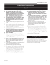
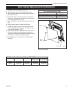
Electrical Wiring Diagram
Operating Instructions
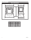
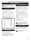
Main On/Off Switch
The On/Off switch supplies power to
all of the functions of the stove. It is
located on the back of the unit.
NOTE: The On/Off switch must be
in the ON position when using the
remote control.
WARNING: During any service of
this appliance, the power to the
unit must be turned off. It is not ac-
ceptable to use the “On/Off” switch
to meet this requirement.
The Heater Control acts to turn the
heater on and off as well as setting
the comfort level in the room. Turn-
ing the knob clockwise from the off
position will place the heater into
operation. The further the knob is
rotated clockwise, the higher the set
point temperature. Turning the knob
counterclockwise will lower the set
point temperature. Turning it all the
way counterclockwise will turn the
heater function off.
Heater Control
BLACK
WHITE WIRE
REMOTE RECEIVER
HEATER
MOTOR
HEATER
BLACK WIRE
SWITCH OFF/ON
THERMOSTAT
WHITE WIRE
GENERATOR
FLAME
MOTOR
GREEN WIRE
RED WIRE #1
BLACK WIRE
WHITE WIRE #2
BLACK WIRE
BLACK WIRE #7
L IN
BLACK WIRE
BLACK WIRE
BLACK WIRE #
6
WHITE WIRE #3
WHITE WIRE #4
WHITE WIRE #5
RED WIRE LINE
N IN
N OUT
L OUT
BLACK WIRE #9
BLACK WIRE
#8
BLACK WIRE # 10
BLACK W
IRE #11
RED WIRE #13
WHITE WIRE #12
WHITE WIRE WIRE
ST828
Addison wiring
rev 1 En
9/04
ST828
HS101
Heater Control
5/02
ON/OFF
Switch
Temperature
Control
HS101
Fig. 4 Control locations at the top rear
corner of the stove.