


- 10 -
For some installations, it may be desireable
to have some amount of the horizontal vent
run immediately after the fireplace. A verti-
cal rise must be used but can be located
anywhere in the vent system, to meet the
perimeters identified in the venting graph.
*IMPORTANT* Minimum clearance between vent pipes
and combustible materials is one (1") inch (25 mm) on
bottom, sides and top.
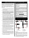
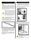
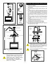
Join pipes and secure joints with three (3) sheetmetal
screws. (See Fig. 12) Wipe off excess sealant.
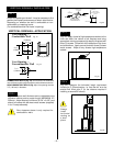
GENERAL INFORMATION ON ASSEMBLING
THE VENT PIPES WITH CRIMPED ENDS
BEAD LOCATION
1" FROM CRIMPED END OF PIPE
1''
Screw Holes
Only Majestic venting components
specifically approved and labelled for
this fireplace may be used.
Fig. 12
Before joining elbows and pipes apply a bead of high
temperature sealant to crimped end of 4" and 7" elbow or
pipe. (Fig. 12)
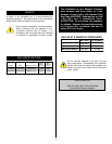
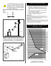
Since it is very important that the venting system
maintain its balance between the combustion air intake
and the flue gas exhaust, certain limitations as to vent
configurations apply and must be strictly adhered to.
The graph showing the relationship between vertical and
horizontal side wall venting will help to determine the
various vent lengths allowable. Fig. 17.
Vent Starter Kit 7DVSK must be used in
Vertical Sidewall installations.
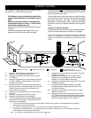
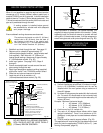
VERTICAL SIDEWALL APPLICATIONS
Minimum clearance between vent pipes and
combustible materials is one (1") inch (25
mm) on top, bottom and sides unless
otherwise noted.
When vent termination exits through
foundation less than 20" below siding outcrop,
the vent pipe must flush up with the siding. A
7DVSS must also be used.
It is always best to locate the fireplace in such a way that
minimizes the number of offsets and horizontal vent
length.
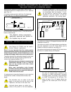
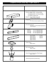
The horizontal vent run refers to the total
length of vent pipe from the flue collar of the
fireplace to the face of the outer wall.
Horizontal plane means no vertical rise
exists on this portion of the vent assembly.
Fig. 13
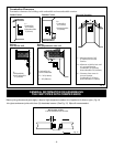
The maximum number of 90 degree elbows per side wall
installation is three (3).
The maximum number of 45 degree elbows permitted per
side wall installation is two (2). These elbows can be
installed in either the vertical or horizontal run.
The maximum horizontal vent length is 36" (914mm) when
90º elbow is installed directly onto fireplace.
Fig. 14
For each 45 degree elbow installed in the
horizontal run (while maintaining a constant
horizontal plane), the length of the horizontal
run MUST be reduced by 18" (457mm). This
does not apply if the 45 degree elbows are
installed on the vertical part of the vent sys-
tem.
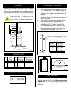
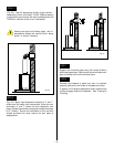
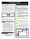
20 ft. (6100mm)
90" (2286mm)
PIPE STRAPS
EVERY 3 ft.
(914mm)
PIPE STRAPS
EVERY 3 ft.(914mm)
FIRESTOP/ZERO
CLEARANCE SLEEVE
3 FT
(92cm)