


- 15 -
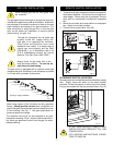
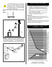
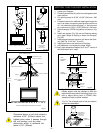
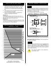
TYPICAL STRAIGHT-UP INSTALLATION
40 FEET
(12.2m)
ATTIC INSULATION
SHIELD
JOISTS
ROOF
VENT TERMINATION
ATTIC INSULATION
ROOF SUPPORT
STORM COLLAR
ROOF FLASHING
2' Min.
CEILING JOISTS
Fig. 33
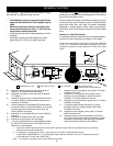
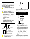
1. Locate your fireplace.
2. Plumb to centre of the (4") collar from ceiling above and
mark position.
3. Cut opening equal to 9-3/8" x 9-3/8" (240 mm x 240
mm).
4. Proceed to plumb for additional openings through the
roof. In all cases, the opening must provide a minimum
of 1 inch clearance to the vent pipe, i.e., the hole must
be a minimum of 9-3/8" x 9-3/8" (240 mm x 240 mm).
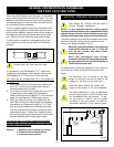
5. Place firestop(s) 7DVFS into position and secure. (Fig.
32)
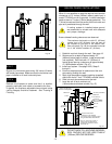
6. Install roof support (Fig. 30) and roof flashing making
sure upper flange of flashing is below the shingles.
(Fig. 33)
7. Install appropriate pipe sections until above the flash-
ing. (See Fig. 31 for #'s 7, 8 and 9).
8. Install storm collar and seal around the pipe.
9. Add additional vent lengths for proper height.
10. Apply high temperature sealant to 4" and 7" collars of
vent termination and install.
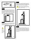
VERTICAL THRU THE ROOF INSTALLATION
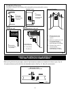
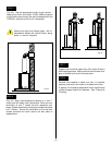
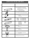
Fig. 32 If there is a room above ceiling level,
firestop spacer must be installed on both the
bottom and the top side of the ceiling joists. If an
attic is above ceiling level a 7DVAIS (Attic
Insulation Shield) must be installed.
Fig. 33. The enlarged ends of the vent section
always face downward.
SEALANT
SHEETMETAL
SCREWS (#5) —
3 PER JOINT
STORM
COLLAR
JOIST
11"
11"
Attic
Insulation
Shield
Ceiling
Installation
JOIST
NAILS (4)
FIRESTOP
SPACER
11"
11"
UPPER FLOOR
Fig. 32
Fig. 29
Fig. 30
TYPICAL 7DVCS
APPLICATION
TYPICAL ROOF
SUPPORT
APPLICATION
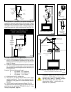
Fig. 31
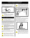
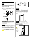
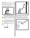
Fig. 28
Clearance above a roof shall extend a
minimum of 24" (610mm) above the
highest point when it passes through
the roof surface, and any other
obstruciton within a horizontal dis-
tance of 18" (450mm).
45°
45°
2438mm
MAX.
8 FEET
2438mm
MAX.
8 FEET
TYPICAL OFFSET INSTALLATION
40 FEET
(12.2m)