


8 10004894
LHEDV Series Direct Vent Insert
FP1330
Switch assy
4/03
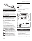
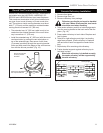
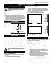
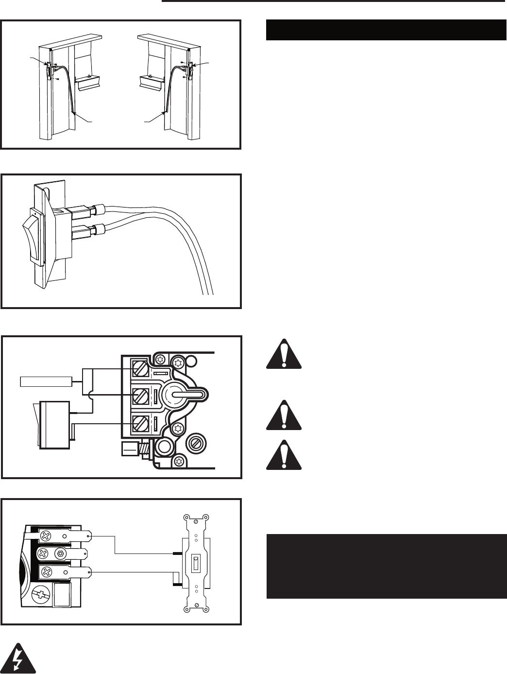
Left Side Installation
Right Side Installation
On/Off
Switch As-
sembly
Wiring from
Millivolt Gas
Valve
Fig. 7 Insert ON/OFF switch with wiring assembly into
bracket switch.
On/Off
Switch As-
sembly
FP1330
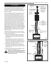
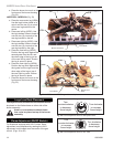
Installer must attach red warning plate
with screws supplied with the gas fireplace
insert to the inside of the firebox of the
fireplace into which the gas fireplace insert
is installed.
Cutting any sheet metal parts of the fire-
place, in which the gas fireplace insert is
to be installed, is prohibited.
If the factory-built fireplace has no gas
access hole(s) provided, an access hole of
1¹⁄₂� (38 mm) or less may be drilled through
the lower sides or bottom of the firebox in
a proper workmanship-like manner. This
access hole must be plugged with a non-
combustible insulation after the gas sup-
ply line has been installed.
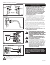
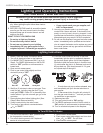
CAUTION: Do not wire millivolt remote
wall switch for gas fireplace to a 120v
power supply.
P
I
L
O
T
THTP
TP
TH
FP382a
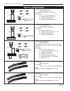
REMOTE SWITCH WIRING - NVC
1/03
SIT Valve
Thermopile
FP382a
Fig. 9a On/Off switch or millivolt thermostat.
TPTH
TH
TP
FP1218
Remote switch
wiring
8/02
FP1218
Fig. 9b On/Off switch wiring.
Honeywell Valve
Fig. 8 For left side installation, reverse switch position in
bracket.
FP1331
on/off switch
4/03
FP1331
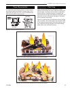
WARNING
Some factory-built fireplaces have air passages
on face of fireplace for zero clearance capabilities.
Under no circumstances should these passages
be blocked.
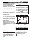
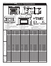
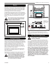
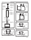
Venting Installation
1. The fireplace may be installed in and vented
through any solid fuel fireplace that has a minimum
fireplace opening 25¹⁄₄"W x 17¹⁄₂" H x 13¹⁄₂"D (641
x 438 x 343 mm) for LHECDV20 and LHERDV20 or
28³⁄₄"W x 21"H x 15¹⁄₂"D (730 x 533 x 394 mm) for
LHECDV30 and LHERDV30 and has been installed
in accordance with the National, Provincial/State
and local building codes and is constructed of
noncombustible materials.
2. Only HEDVRT RD vent termination kit, HEDVT (8 x
12) or HEDVT (12 x 12) termination kit and flex vent
kit HEDVK25 or HEDVK35 are to be use din this
installation. Under no circumstances should B
vent or C vent be used on this application.
3. Any flue damper must be removed or blocked open.
5. The chimney must be clean and in good working
order and constructed of noncombustible materials.
6. Make sure that all chimney cleanouts fit properly so
air cannot leak into the chimney.
7. Install the appliance without trim frame and make all
gas fittings and electrical connections.
8. Install the decorative trim frame. Please refer to the
Frame Assembly instructions.