


23
Pinnacle & Stardance Direct Vent - Rear Vent Gas Heaters
20007066
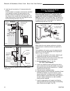
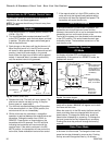
Connect the Gas Supply Line
Burner Information
The appliance must only use the gas specified on the
rating plate, unless converted using a Vermont Castings
Fuel Conversion Kit. Refer to Page 41 for correct Fuel
Conversion Kit for your stove model.
Coversion instructions are provided with each kit and
beginning on Page 33 of this manual.
In order to connect Natural Gas, use a fitting with a
3/8” NPT nipple on the valve side and 1/2” natural gas
supply line with an input of 21,000 BTU’s at a manifold
pressure of 3.5” and minimum inlet supply for
adjustment of 5.5” w.c.
In order to connect Propane, use a fitting with 3/8”
NPT nipple on the valve side and 1/2” propane gas
supply line with an input of 21,000 BTUs at a manifold
pressure of 10.0” and minimum inlet supply for
adjustment of 11.0” w.c.
Check the rating plate attached by a steel cable to the
firebox, to confirm that you have the appropriate
firebox for the type of fuel to be used. The PDV20 and
SDVR may be converted from one gas to another
using the appropriate Fuel Conversion Kit listed on
Page 41.
This appliance should only be
connected by a qualified gas
technician. Test to confirm manifold
pressures as specified below.
The PDV20 and SDVR Heaters and the individual
shutoff valves must be disconnected from the
gas supply piping during any pressure testing of
that system at test pressures in excess of 1/2
psig (3.5 kPa).
The PDV20 and SDVR Heaters must be isolated
from the gas supply piping system by closing
the individual manual shutoff valve during any
pressure testing of the gas supply piping system
at test pressure equal to or less than 1/2 psig.
There must be a gas shutoff between the stove
and the supply.
In order to connect Natural Gas, use a fitting
with 3/8” NPT nipple on the valve side and 1/2”
natural gas supply line with an input of 21,000
BTUs at a manifold pressure of 3.5” and mini-
mum inlet supply for adjustment of 5.5” w.c.
In order to connect Propane, use a fitting with 3/
8” NPT nipple on the valve side and 1/2” propane
gas supply line with an input of 21,000 BTUs at a
manifold pressure of 10.0” and minimum inlet
supply for adjustment of 11.0” w.c.
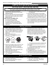
CAUTION
THIS APPLIANCE SHOULD BE CONNECTED TO
THE GAS SUPPLY ONLY BY A QUALIFIED GAS
SERVICE TECHNICIAN. FOLLOW ALL LOCAL
CODES.
THERE MUST BE A GAS SHUT-OFF BETWEEN
THE STOVE AND THE SUPPLY.
In the U.S.: Gas connection should be made in
accordance with current National Fuel Gas Code, ANSI
Z223.1/NFPA 54. Since some municipalities have
additional local codes, be sure to consult your local
authority.
In Canada: consult the local authority and CSA-B149.1
installation code.
Connect the gas supply and test for leaks. Use a mild
soap and water solution applied with a brush no larger
than 1” (25mm). Never apply soap and water solution
with a spray bottle. Do not use an open flame for leak
testing.
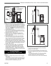
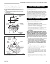
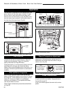
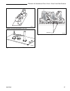
Complete the Assembly
• Open the swiveling latches (cams) on the top left
and right corners of the glass frame.
• Position the glass and frame against the firebox by
placing the bottom edge on the brackets on the
bottom face of the firebox.
• Swing the assembly against the firebox, and close
the latches firmly against the pins protruding from
the firebox top.
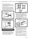
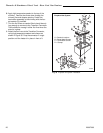
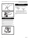
Install ON/OFF Switch (R Models ONLY)
The switch assembly parts are found in the parts bag.
1. Attach switch assembly to left rear side of stove
shroud using two screws and existing holes in
shroud. (Fig. 40)
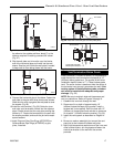
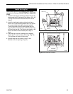
2. Run wires down back of stove, under bottom of rear
shroud to valve.
3. Attach wires to valve terminals. (Fig. 41)