


35
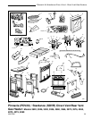
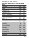
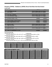
Pinnacle & Stardance Direct Vent - Rear Vent Gas Heaters
20007066
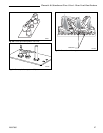
NOTE: Be sure burner leg remains at a 90° angle to
firebox base after conversion.
Models 3960, 3970, 4075, 4080 (RF Models) Only
16. Follow procedure for pilot type 2 to replace pilot
orifice.
17. Remove and replace plug on lower right hand side
of the valve; Red for LP and Blue for NG. (Page 30,
Fig. 53)
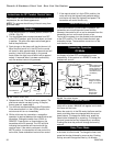
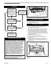
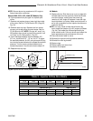
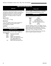
18. Remove motor top cap. Depress and turn center
plunger until arrow points to correct screw. Red for
LP and Blue for NG. NOTE: Plunger will “snap” into
NG position when arrow is close to blue screw. It will
not “snap” at LP (Red) position. (Fig. 63)
19. Insure manifold pressure remains between 3.2” -
3.5” w.c. for NG and 9.5” - 10” w.c. for LP. To adjust
the manifold pressure, for NG, using a torque #10 key
turn the blue screw clockwise to increase the manifold
pressure. Turn the screw counterclockwise to de-
crease the pressure. Use the red screw to adjust LP.
20. Replace motor top cap.
All Models
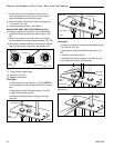
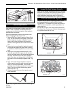
21.Replace burner. Slide the burner in at an angle with
left side lower than the right side. Slide the left side
onto the injectors, making sure the burner leg
remains at a 90° angle to the base. Lower the right
hand side down in to place. Make sure the burner is
as far left as possible and the injector shoulders are
inside the burner.
NOTE: It is very critical to keep the left burner leg,
which holds the injectors, at a 90° angle to the base.
(Fig. 64) This keeps the orifices aligned with the
tubes inside burner. Failure to do so could affect the
flame appearance and performance of the unit.
22.Place conversion label on valve.
23.Reinstall the right and left log bracket assembly.
24.Reinstall the rear log bracket.
25.Replace logs.
25.Replace glass and stove front.
Conversion is complete.
LOCAL
Center
Plunger
Motor Top Cap
Red - LP
Blue - NG
FP1037b
Fig. 63 Depress and turn center plunger.
Valve
90°
Left Burner Leg
Injector Orifices
ST353a
Fig. 64 Remove and replace injector orifices.
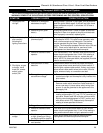
Conversion to LP Input (BTU/h)
Kit # Front Part # Rear Part # Minimum Maximum
000-5005 #68 / .031” 30000694 #56 / .0465” 30000336 14,000 21,000
000-5014 #68 / .031” 30000694 #56 / .0465” 30000336 14,000 21,000
Table 2. Injector Orifice Size Matrix
Conversion to Natural Gas Input (BTU/h)
Kit # Front Part # Rear Part # Minimum Maxi,mum
000-5004 #56 / .0465” 30000336 #47 / .078” 20003054 14,000 21,000
000-5013 #56 / .0465” 30000336 #47 / .078” 20003054 14,000 21,000