SKU 65760 For technical questions, please call 1-800-444-3353. Page 7
SPECIFICATIONS
Electrical
Requirements
110 V~ / 60 Hz / 8 Amps
Power Switch: Trigger with Safety Lock
Power Cord: 16 AWG x 2C
Power Plug: GFCI 2-Prong Polarized
Rotation Counterclockwise Only
Rotations Per
Minute
Low Speed (l): 0 to 500 RPM
High Speed (ll): 0 to 700 RPM
Variable Speed 6 settings
Accessories
Left Auger (Qty. 1)
Right Auger (Qty1)
Carbon Brushes (Qty. 2)
7/8” Wrench (Qty. 1)
1-1/8” Wrench (Qty. 1)
UNPACKING
When unpacking, check to make sure
that the item is intact and undamaged. If
any parts are missing or broken, please
call Harbor Freight Tools at the number
shown on the cover of this manual as soon
as possible.
ASSEMBLY INSTRUCTIONS
Read the ENTIRE IMPORTANT
SAFETY INFORMATION
section at the beginning of this
manual including all text under
subheadings therein before set
up or use of this product.
TO PREVENT
SERIOUS INJURY
FROM ACCIDENTAL
OPERATION:
Turn the Power Switch (1) of
the Mortar Mixer to its “OFF”
position and unplug the tool
from its electrical outlet
before assembling or making
any adjustments to the tool.
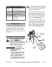
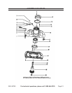
Note: For additional information regarding
the parts listed in the following pages,
refer to the Assembly Diagram near
the end of this manual.
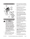
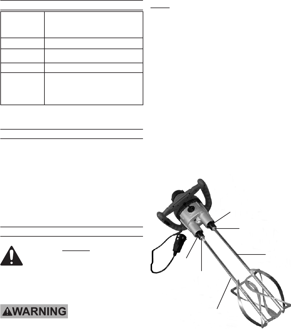
Insert the Left Auger (28A) into the 1.
Output Shaft (27) marked “L”. Then
use the provided 7/8” Wrench (28C)
and 1-1/8” Wrench (28D) to tighten
the Nut (29) and secure the Left Au-
ger in place. (See Figure A.)
Insert the Right Auger (28B) into the 2.
Output Shaft (27) marked “R”. Then
use the provided 7/8” Wrench (28C)
and 1-1/8” Wrench (28D) to tighten
the Nut (29) and secure the Right
Auger in place. (See Figure A.)
FIGURE A
NUT
(29)
NUT
(29)
OUTPUT
SHAFT
(27)
OUTPUT
SHAFT
(27)
LEFT
AUGER
(28A)
RIGHT
AUGER
(28B)


