


1-29
Cisco Metro 1500 Series Hardware Installation Guide
78-10588-03
Chapter 1 Product Overview
System Modules
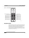
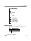
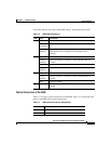
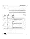
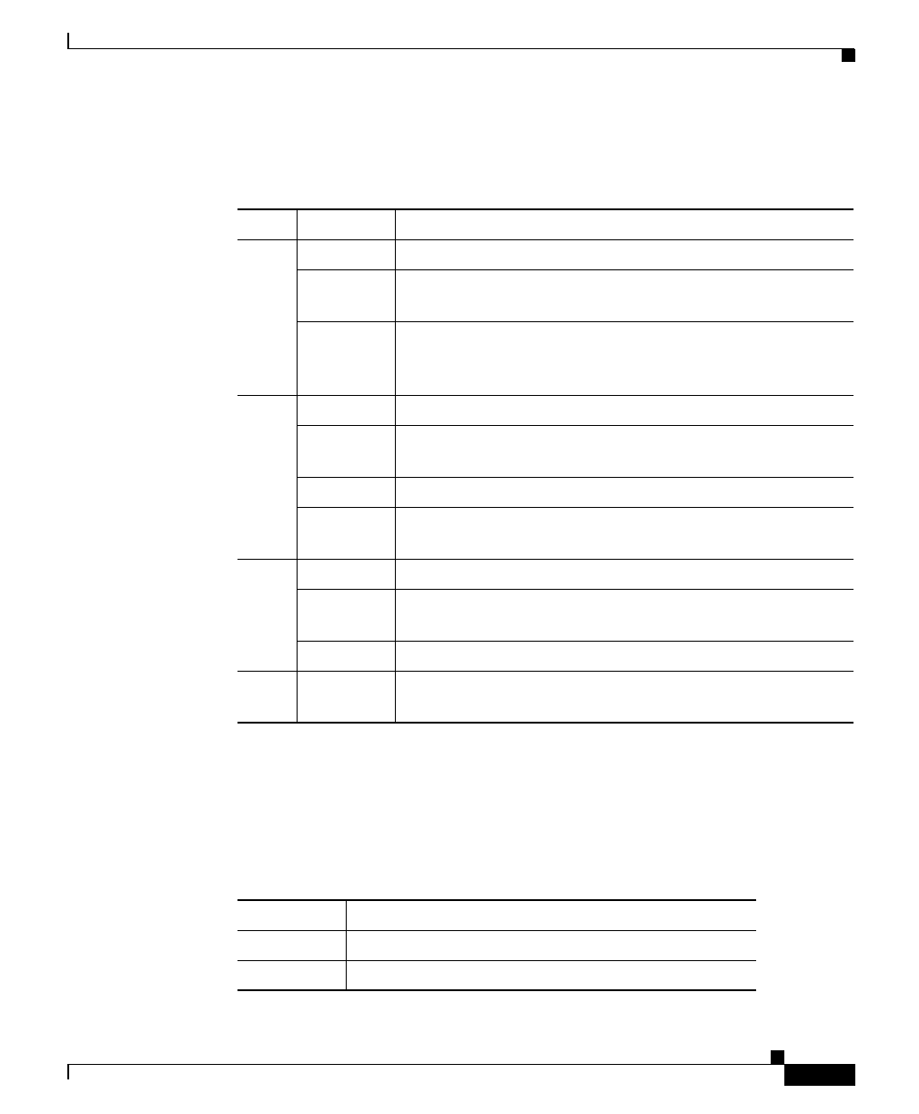
Four LEDs indicate the status of the RSM. Table 1-6 describes these LEDs.
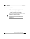
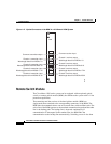
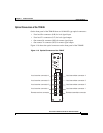
Optical Connectors of the RSM
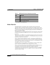
Table 1-7 lists the six optical connectors of the RSM. Figure 1-13 shows the front
panel of the RSM and its optical connectors.
Table 1-6 RSM LED Descriptions
Label Color Description
On Green Power is on. No error is detected.
Red,
continuous
A hardware error is detected.
Red,
blinking
Loss of signal is detected on both remote lines of the RSM.
Both remote lines are broken or a hardware error is
detected.
A Green Line A is active.
Green,
blinking
Line A is inactive. A takeover of the communication is
possible.
Red Line A is broken and active.
Red,
blinking
Line A is broken and inactive.
B Green Line B is active.
Green,
blinking
Line B is inactive. A takeover of the communication is
possible.
Red Line B is broken.
L
k
Yellow RSM is locked to one line. No automatic switching is
possible.
Table 1-7 RSM Optical Connector Descriptions
Label
1
Description
A/T Line A transmitter
A/R Line A receiver