


Chapter 1 Product Overview
Communication Channels
1-6
Cisco Metro 1500 Series Hardware Installation Guide
78-10588-03
Expansion Modules
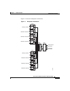
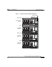
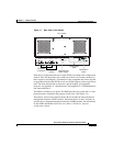
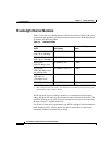
The Cisco Metro 1500 series system requires two identical WCMs to complete a
full communications link, one at each end of the link. Each system unit includes
a primary chassis (see Figure 1-3) that holds up to eight WCMs. The WCMs
transport up to eight independent channels.
Figure 1-3 Primary Chassis
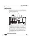
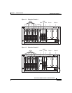
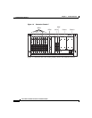
The Cisco Metro 1500 series system can be expanded by adding more WCMs.
Adding extension chassis A, B, and C (Figure 1-4 to Figure 1-6) at both ends of
the communications link upgrades the system to transport a total of 32
independent channels. A network element management interface (NEMI) can
control up to two chassis and up to four NEMIs can be combined through an
Ethernet hub or switch to appear as a single system as seen by a Network
Management System (NMS). We recommend that you initially install the primary
chassis and extension chassis A, which holds the BSM, to avoid service
interruption while upgrading the unit to more than eight channels. The primary
chassis and the extension chassis are each equipped with two fully redundant
load-sharing, hot-swappable power supply modules (PSMs), as shown in
Figure 1-3 to Figure 1-6.
WCM
RSM
MUX
Power 1
Power 2
NEMI
DMX
FAIL
POWER
OK FAILOK
FAN
L/T
R/T
R/R
L/R
Loop
On/Err
L/T
R/T
R/R
L/R
L/T
R/T
R/R
L/R
Loop
On/Err
L/T
R/T
R/R
L/R
L/T
R/T
R/R
L/R
Loop
On/Err
L/T
R/T
R/R
L/R
L/T
R/T
R/R
L/R
Loop
On/Err
L/T
R/T
R/R
L/R
L/T
R/T
R/R
L/R
Loop
On/Err
L/T
R/T
R/R
L/R
L/T
R/T
R/R
L/R
Loop
On/Err
L/T
R/T
R/R
L/R
L/T
R/T
R/R
L/R
Loop
On/Err
L/T
R/T
R/R
L/R
L/T
R/T
R/R
L/R
Loop
On/Err
L/T
R/T
R/R
L/R
Auto
L B
k
L A
k
L
k
A
On
B/T
B/R
M
D
A/T
A/R
B
Power
Error
Err.Int.BUS
Err.Ext.BUS
Receive
Link
BUS 1
BUS 2
Serial
Net
1-8(32) 1-8(32)
MUX DMX
7
8
M1
nc
7
8
5
6
3
4
1
2
D1
nc
7
8
5
6
3
4
1
2
on
Power
on
Power
I
0
METRO 1500 SERIES
39943