


INSTALLATION MANUAL
SteamChef MODELS 22CGT3 AND 22CGT6
TABLE OF CONTENTS
Chapter
Page
1 PRODUCT INFORMATION ABOUT 22CGT3 and 22CGT6 SteamChefs…………….. 1
A. Product Information………………………………………………………………………... 1
B. Product Information Plate…………………………………………………………………. 1
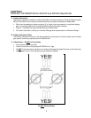
C. Lifting Points – Do NOT
Lift from Sides…………………………………………………. 1
Figure 1-1, Do NOT
Lift from Sides…………………………………………………………. 1
2 GENERAL INFORMATION and INSTALLATION INSTRUCTIONS…..……....………... 2
A. General Information and Installation Instructions……….……………………………… 2
B. Inspect the Appliance for Shipping Damage…………………………………………..... 2
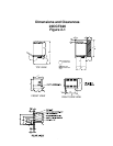
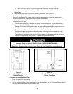
Figure 2-1, Dimensions and Clearances……………………………………………………. 3
3 INSTALLATION of the SteamChef…………………………………………………….…... 4
A. Selecting a Location for the SteamChef……………………………………………….… 4
B. Exhaust Hood Requirements……………………………………………………………... 4
C. Install the Legs……………………………………………………………………………... 5
Figure 3-1, Steamer on Foam Packing Blocks, Top View………………………………… 5
Figure 3-2, Steamer on Foam Packing Blocks, Front View…………………………….… 5
D. Position and Level the SteamChef……………………………………………………….. 5
E. Gas Supply For the SteamChef…...……………………………………………………... 6
1. Gas Supply Requirements…………………………………………………………….. 6
2. Installation of the Gas Supply Lines…………………………………………...….….. 6
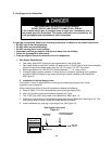
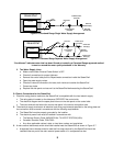
Figure 3-3, Gas Supply Line Layout………………………………………………………… 6
3. Testing Gas Supply Lines…………………………………………………………….... 7
4. Pressure Testing the Gas Supply Lines……………………………………………… 7
F. Water Connections for the SteamChef…………………………………………………... 7
1. Water Supply Quality Requirements…..……………………………………………... 7
2. Connection of the Water Supply Lines……………………………………………...... 8
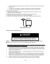
Figure 3-4, Filter Washer……………………………………………………………………... 8
Figure 3-5, Single Water Supply Arrangement…………………………………………….. 9
Figure 3-6, Separate Water Supply Arrangement…………………………………………. 9
3. Test Water Supply Lines……………………………………………………………….. 9
G. Electric Connections for the SteamChef………………………………………………… 9
Figure 3-7, Main External Power Switch……………………………………………………. 10
H. Install the Free Air Vented Drain Line.....…..……………………………………………. 10
Figure 3-8, Typical Drain Layout…………………………………………………………….. 11
I. Install the Fan Guard……………………………………………………………………….. 11
J. Install the KleanShield™…………………………………………………..…………........ 12
K. Install the Slide Racks (Pan Racks).…………………………………………………..…. 12
Figure 3-9, Cooking Compartment………...………………………………………………… 12
L. Installation Check List……………………………………………………………………... 13