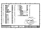
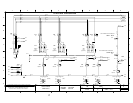
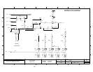
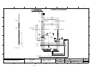
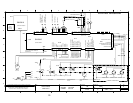
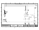
• If the combi fan is in the reduced setting 220 VAC is sent from terminal 6 on
connector X11 through the normally closed auxiliary contacts of contactors
K55 and K56 to the coil of contactor K57
◊ The K57 contactor closes Sending 220 VAC through the Q57 thermal
overload to the motor and the motor turns at a reduced speed.
◊ The normally closed auxiliary contacts of K57 open preventing the K55
and K56 contactors from energizing.
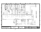
• For the first 2 minutes 220 VAC is sent from terminal 4 on connector X11
through the normally closed auxiliary contacts of contactor K5 to the K50
contactor coil
◊ K50 contactor closes and the motor turns CW
◊ The normally closed auxiliary contacts on K50 open preventing the K5
contactor from energizing.
• For 15 seconds the motor is de-energized and allowed to coast.
• For the next 2 minutes 220 VAC is sent from terminal 3 on connector X11
through the normally closed auxiliary contacts of contactor K50 to the K5
contactor coil
◊ K5 contactor closes and the motor turns CCW
◊ The normally closed auxiliary contacts on K5 open preventing the K50
contactor from energizing.
• NOTE: If the door switch (S7) opens by the door opening, then the fan circuit
is de-energized. Then the motor will be pulsed in the opposite direction to
“break” the fan. This is to stop the fan quicker for the operator.
c The hot air heat circuit is energized
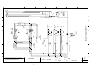
• 220 VAC is sent from terminal 3 of connector X12 on the Control Board
(A10) through the normally closed auxiliary contacts of K2 and K1 to the coil
of Contactor K4 until the cabinet reaches the set temperature as sensed at
probe B6.
◊ The contactor K4 closes and to legs of the 220 VAC is sent to the 18 KW
element (E4)
• 220 VAC is sent from terminal 7 of connector X11 on the Control Board
(A10) to the coil of Contactor K44 until the cabinet reaches the set
temperature.
◊ The contactor K44 closes and the third leg of 220 VAC is sent to the 18
KW element (E4)
◊ If the reduced power option is chosen then the K44 Contactor is not
energized.
d The steam circuit is energized
• 220 VAC is sent from terminal 4 of connector X12 on the Control Board
(A10) to the coil of the Y3 solenoid allowing water to be thrown against the
element until the bypass probe (B5) senses 183 degrees F.
• NOTE: If the set temperature is above 212 degrees F the hot air circuit will be
energized (after the by pass probe is satisfied) until the compartment setting is
reached.
78


